Colour Changing LED chaser circuit using Bicolour LED

Here I am presenting a circuit of 10 dual colour LED flashers (Not using flashing LED) which blink one by one in sequence. This circuit is based on a popular counter circuit using 4017 and 555.
One colour of all LEDS remains fixed, and the second colour of all LEDS in running mode one by one. This gives a very cool and interesting visual lighting effect. The circuit is simple and does not use any microcontroller.
In this LED blinker circuit, 1 IC and 1 CD4017 are used to produce a counting output. 2 NOT GATE inverters are used to change the supply alternately. For changing the colour of the LED by inverting the input supply to the LED.
555 timer ic is used to create a random clocked pulse signal for changing the output through the counter IC 4017. As you know that when the pulse signal at input pin 14 of ic 4017 gets, then according to each clock pulse, the output is on (High)one by one. The output of 4017 is starting from pin 3 (output 0), pin 2 (output 1), pin 4(output 2), pin 7 (output 3) and so on up to pin 11 (output 9 ).
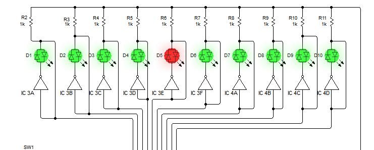
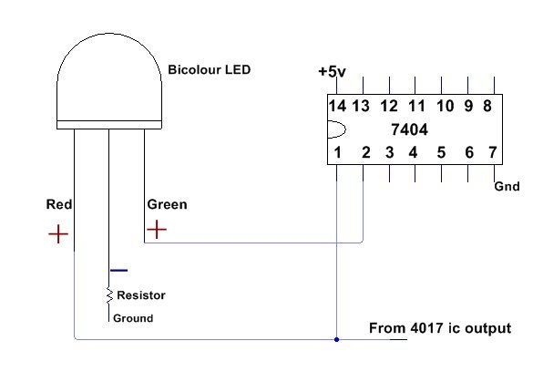
All output of 4017 IC connected with NOT GATE inverter input,t and output of all inverter inputs are also connected with the second pin of bi-colour LED. Not gate inverter is the logic that changes the signal from High to Low or Low to High.
Here, Low means negative or 0 and High means positive or 1.
At first, when the circuit is turned on then all LEDS will glow at a fixed colour, and as soon counter IC 4017 starts counting output then one by one LEDS change their colour in a running effect.
You can understand the working of this as, when the input positive signal gives the 4017 to Inverter input then it converts it in negative and give to led. in this condition only one leg of led get positive supply so only one colour glow because One wire is directly conneted with before inverter input to led input. And when the output of 4017 is Low, then the inverter converts High, and this goes to the second leg of the LED, and only the other colour will glow, and the other is off.
Negative supply of ground (common ) pin of all LEDS connected through 100 ohm resistor. The flashing effect is increased or decreased by changing the value by moving of Variable Resistor VR1 or changing the capacitor value of C1.
This circuit gives a very beautiful running effect light with two colours. Where one colour will be still and the other colour will be running one by one, But Only one colour will blink at a time.
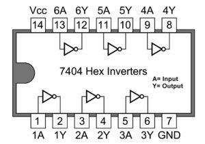
Connect the bicolour LED with 7404 very carefully because if the connection the blinking colour can be mixed. Pin no 1, 3, 5, 9, 11, 13 are input pins, and these are connected with the output pins of 4017. Pin 1 of 7404 is connected with the starting output of 4017 (pin 3) and with one leg of 1st LED. Pin 3 is connected with the 1st output of 4017 (pin 2) and one leg of the 2nd LED……. as follows. All output pins of 7404 are connected to the other leg of the LED. pin 2 with led 1, pin 4 with led 2, pin 6 with led 3……
Use 5v DC supply for this flasher/blinker circuit.
Components
NE555 ic- 1
4017 ic-1
74AC04 (7404) ic-2
Bicolour LED-10
Preset (100K)-1
Resistor
100Ω (1W) -10, 100k-1
Capacitor-
2.2uf 16v-1, 0.1uf-1
More from this blog
-
Touch on-off Switch using 4017
-
Switch ON delay timer circuit
-
Diff between 12-0-12 and 0-12 transformer
-
Operational amplifier (Op-amp)









This is a very interesting topic you have covered. Thank you so much for sharing this here. This simple circuit uses NAND Gates to alternately flash two led’s. The two 47uF capacitors determine the flash frequency. It is a good idea to use a decoupling capacitor across the power supply. I made this circuit using the components shown and it worked fine. The IC that I used is the 4011 Quad 2-input NAND Gate.