LED Flasher Chaser Project Circuit
The LED flasher is very interactive visual lighting and this is very easy to connect with a circuit without any external switching component like relay or Transistor.
Here is a circuit diagram of LED chaser which is very easy to construct and looking very beautiful and interesting.
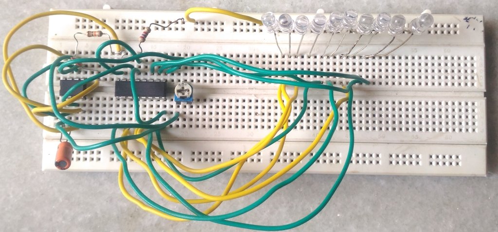
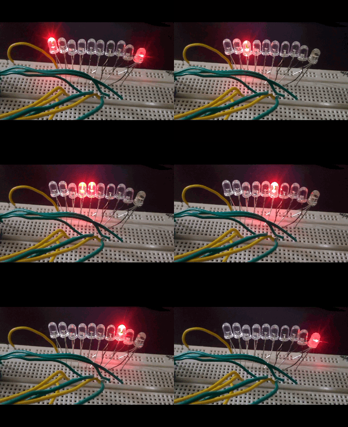
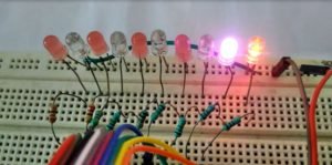
This LED Flasher/Chaser circuit made using very popular ic 555 Timer and 4017 Counter . Total 10 LEDs connected in this circuit (one Extra -optional) . All LEDs are Turn On ONE BY ONE in sequence . If one LED is OFF then Next is ON and so on.
LED Sequence Flashing circuit
Working of Circuit
click here to know about how 4017 works
The 555 ic is connected itself with astable mode and gives a Signal of randomly continuous pulses. When the switch is pressed the switch, the 555 ic gives pulses at output pin 3 with LOW –HIGH randomly (0 1 0 1 0 1…..). and then 4017 ic gets clock signal with each pulse at pin 14 and according to these pulsed signal, it gives the output . whenever pin 14 receives a positive pulse, the counter goes to next.
At first clock pulse, LED1 glows. At second clock pulse output goes from Pin 3 to 2 and LED2 glows and first off and so on.
The speed of flashing can be increased or decreased by changing the value of Capacitor and resistor which is connected with pin 2 of 555, because of changing the value of these the output pulse signal speed varies.
LED Flasher using 4017
Components
LED- 11
LM555 ic-1
4017 ic -1
Capacitor
1uf-1
0.1uf-1
Resistor
10K-1
Preset 500K-1
470 ohm-2




Wow! Finally I got a webpage from where I be able to truly obtain useful facts concerning my study and knowledge.