Sequential 17 LED Chaser circuit Without Microcontroller
LED is the very popular visual decorative lighting thing with very low power consumption. The brightness and looking of colouring combination with multiple LEDs makes an good looking and interesting .
In market there are various types of decorative flashing lights available. Those consume more power. if any parts or components get damaged then it is very difficult to repair and sometime full lighting system can dead by only cause some parts only . This is LED Chaser circuit using 4017 and 555.
We can create and make itself many different designing by assemble these LEDs in a specific flashing operation and then it looks and lighting experience enhanced. We make different flashing operation itself easily by using some electronics components. If any components can damage then easily we can replace itself at home.
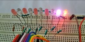
Here i am presenting an circuit for flashing 17 LEDs in a sequence wise. All 17 LEDs turn ON one by one from LED 1 to LED 17 .
In this circuit there are 3 IC are used. One 555 timer ic for provide the pulse frequency to flashing . Two 4017 Counter ic to get sequenced output from it .
I Already discussed about 10 LED Flasher circuit using single 4017 ic and 555 timer. That circuit was used to only 10 LED operation. But here two 4017 ic combined to each other and output is increased to 17 usable output.
Connect All components carefully as given in circuit diagram. Pin no 8 of both 4017 ic is connect with negative supply (ground) . Pin no 3 of ic2 U2 is not connected . Pin 15 of U2 is connected with pin no 11 of U3 . Pin no 13 of U2 is directly connected with pin 11 of same ic.
Only 9 output of U3 is used because in this circuit pin no 3 produce not required sequenced output so , this pin keep open. Pin 14 of U2 is connect with output of 555 but pin 14 of u3 is connected with the transistor collector.
 555 timer ic is used for giving pulse signal on U2. Any other circuit can used for giving pulse signal . By some modification with LED arrangement and ckt you can make more different interesting pattern.
You can use 230v bulb also at the place of LED with use of Relay with each bulb separately.
Speed of Flashing can be changed by adjusting of moving R1 preset.
Video of Output of This Project
Components
IC
555-1
4017-2
LED-17
Resistor
10k-2
1k-5
2.2k-1
Transistor
BC547-3
Preset-500k-1
Capacitor
1uf 25v-1
0.1uf (104)-1
0.01uf (103)-1






Lovely just what I was searching for. Thanks to the author for taking his time on this one.