Delay Timer For Switch ON Supply To Any Appliance For Protection
Circuit 1
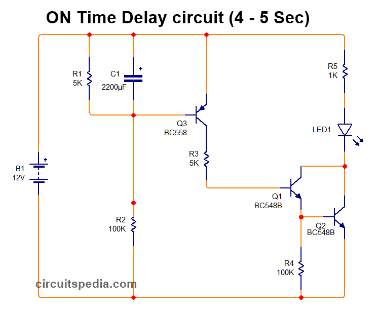
power on delay timer circuit
The delay timer is a device that is used to take some duration be]fore switch on the main input supply to any equipment. This is a protection circuit to protect any electrical or electronic equipment and appliance from sudden high or unstable voltage.
Delay timer takes on hold the supply some moment and then starts to flow. This is done by using the Relay in Delay timer circuit. Here I present a very easy and simple circuit of ON Time delay timer circuit which is made using 2 transistors, some resistors, and a capacitor. In this circuit, no any timer ic is used, so the construction of this project is easy.
Use at least a minimum 2200uf 25v capacitor and connect a 5k ohm resistor to the parallel of this capacitor for discharging fastly. When switching on the circuit then the capacitor starts charging and the amount of power goes to the capacitor till charge, after some seconds it get fully charged. After the capacitor gets fully charged then the current starts to go to the PNP transistor BC558 and through the 100k resistor at the base of this transistor, it gets turned on, and then the supply passed through this transistor and goes to the NPN BC548 through 5k resistor. And this transistor is also turned on and the Connected relay is activated now. The Timing delay is produced by the charging time duration of the capacitor. When switch off this circuit, the capacitor is discharged and it ready for next time to provide delay time.
I suggest using a small size PCB Relay of 12v 20A. If you want more time duration then connect more than 2200uf value capacitor or connect more with parallel.
Components
Capacitor 2200uf 25v-1
Resistor
5k -2
1k-1
100k-2
Transistor
BC558-1
BC548-1
Circuit 2
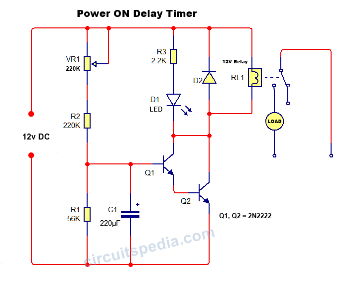
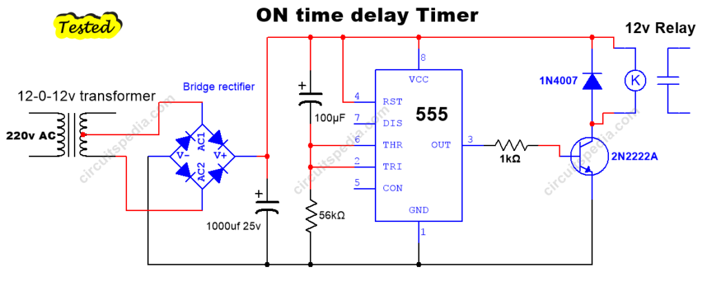
This circuit is working on the charging and discharging duration of capacitors. 56K resistor is used in the circuit for the discharging of capacitor C1. Transistor Q1 will get a small voltage at its base terminal for turning on and this single transistor gives very less current that not be able to activate the relay so another transistor is connected with the emitter of the first transistor to make high output current. this combination of two transistors is called the Darlington pair. In the Darlington pair of transistors, the base of the 2nd transistor will get a small voltage from the emitter of the 1st transistor. in this pair, the output will become higher.
Parts
Resistors
220K-1, 56K-1, 2.2K- 1
Preset 220K-1
Capacitor 220uf 25v -1
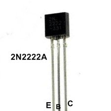
Transistor 2N2222 – 2
Relay 12v
Diode 1N4007 -1
LED-1
Also read
How Capacitor block DC but passes AC
Solid-state Relay using TRIAC and Optocoupler
