Delay OFF Timer circuit For OFF time Delay , Switch OFF Delay Timer
Timer Circuit For Automatic Switch OFF Any appliance After a fix Time Duration.
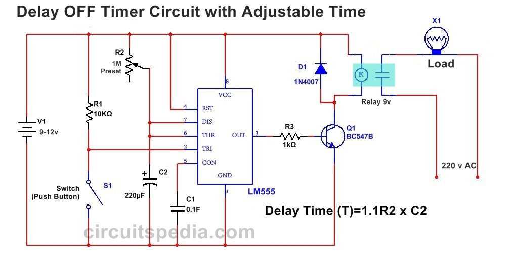
When switch S1 is pressed then Output Will Give HIGH signal at pin 3 and Transistor is ON , Therefore the connected load with relay is also switched on. But After some time the output at pin 3 is automatically goes to LOW and then the load is automatically Switch OFF. Connected Appliance with this timer circuit is automatic switch OFF after some duration of time. The delay duration can adjusted with the changing the value of R2 and Capacitor c2. The Changing of capacitor value is not easy so only the changing of value of the resisitor by variable resistor preset is connected with the circuit to setting the delay time duration delay time.
Working
This connection of circuit is called the Monostable Mode of operation. In Monostable Operation the output is given by the 555 timer is One shot . When the trigger pulse applied at pin 2 then The output is produced by the circuit is HIGH for a fix time in this mode. Output voltage Remain High Only for Fix time duration . Trigger pulse is Detected by the Negative supply at pin no 2.
When switch S1 is pressed then a trigger pulse applied by the connection between the Negative supply (0v) at the pin no 2 and this get triggered and the output is become High .
When a negative trigger is applied on the Trigger input pin 2of 555, output goes high and capacitor starts charging through resistor . When the capacitor voltage becomes greater than 2/3 Vcc, ouput goes low and capacitor starts discharging through the Discharge pin of 555 Timer. Time period of the unstable state is given the expression, T = 1.1 x RC. And awaiting another trigger pulse to start the timing process over again. Then as before, the Monostable Multivibrator has only “ONE” stable state.
This Delay timing Behaviour of 555 is used in many application, You can use this to operated any high power Load by connecting suitable Transistor and Relay
The Timing duration can adjusted by the adjusting of preset by moving it .The time duration can found by the given formula.
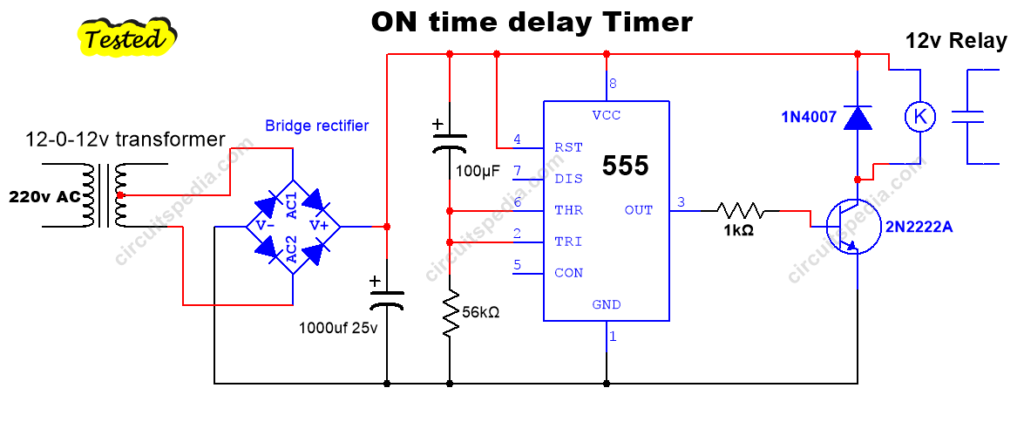
Must Read Delay ON Timer circuit
Also Read Touch Doorbell Alarm Switch Without IC


Hello!
Thanks for the circuit! I have question about the operating time, i.e. the formula.
You said T = 1.1 x RC, but what are the units? R=ohms, K-ohms, M-ohms, etc, C=F, uF, nF, pF?
T = seconds, minutes, hours, etc. …?
Thanks!
T is in seconds
R is in Ω and C in Farads.
nice ccircuit but can this be revised and remove the switch., so that when power is applied, the relay closes and then opens at a predetermined time?