Contents
Norton’s theorem statement
In Thevenin theorem, we see that in any complex circuit sources are converted in single voltage source Vth with the Series resistor Rth. Norton’s theorem is also a method to convert any complex network into a simple circuit.
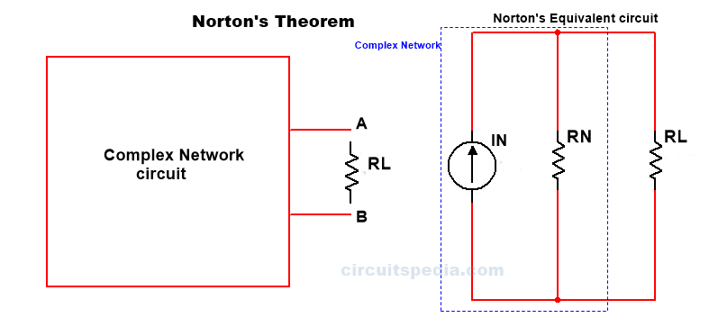
Norton Theorem, any two-terminal complicated network circuit can be converted in single Current source IN in parallel with a single resistor RN.
Actually in norton we convert any complex or complicted circuit into a simple circuit and I get current value across a Load
According to Norton theorem, Any linear bilateral network irrespective of its complexities can be reduced into Norton’s equivalent circuit having a Norton short circuit current “Ir” in parallel with Norton’s equivalent resistance Rn in parallel with load resistor RL.
What is Load resistor – Across which resistor asked to find the current that resistor is called Load resistor.
Steps for solving the Norton theorem problems
Step1. Identify the load resistor RL.
Step 2. Replace RL with a short circuit at this place. The current flowing through this short circuit branch will be Norton’s current IN. This current also is known as short-circuited current Isc.
Step 3. Remove the load resistance and replace all the active sources with their internal resistance.
Step 4. The equivalent resistance across the two open will be Norton’s resistance RN.
Step 5. Draw Norton’s equivalent circuit.
Step 6. Calculate IL using the identity IL=IN.RL/RN+RL
Example 1
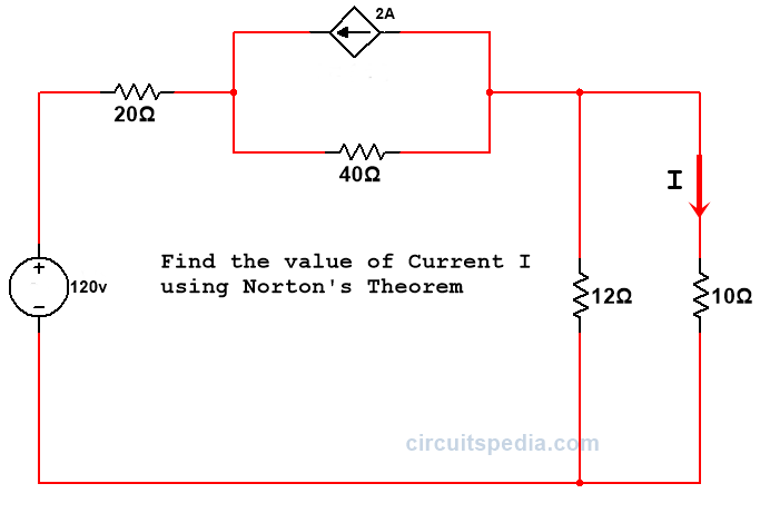
Q.1 Find the value of current I in the given circuit using Norton’s theorem
Solution –
Here RL= 10Ω
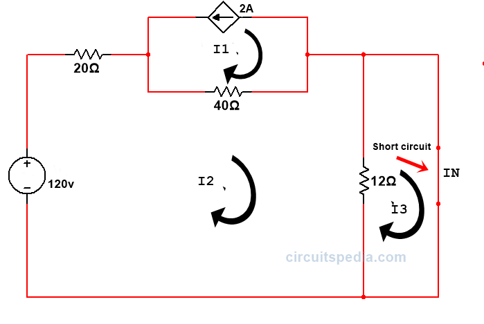
Now I Replace the Load resistor with short circuit and Apply the KVL
I1=-2A
40I1-72I1+12I3=-120
Putting the value of I1
-80-72I2+12I3=-120
-72I1+12I3=-40 ———-Eq.1
And, -12I3+12I2=0 ———Eq.2
by solving the eq 1 & 2
I2=0.666A
Because of 10Ω resistor is short-circuited then 12Ω resistor also should be shorted, and then we don’t need to find the current at IN.
Current I2 is passed across IN.
So,IN=I2=0.666A
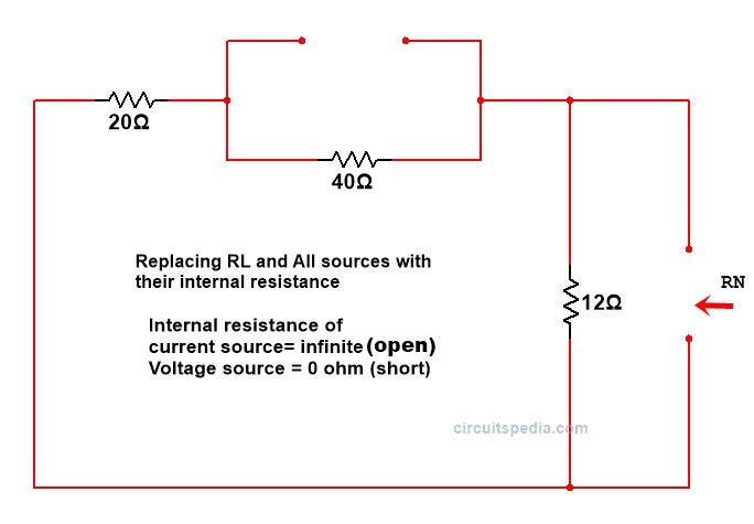
Now we Remove the Load resistor RLK and repace all sources with their internal resistance.
RN=(20+40)//12
RN=60*12/60+12
RN=10Ω
by using Norton Identity
IL=IN.RL/RN+RL
IL=0.333A (Ans)
Example 2
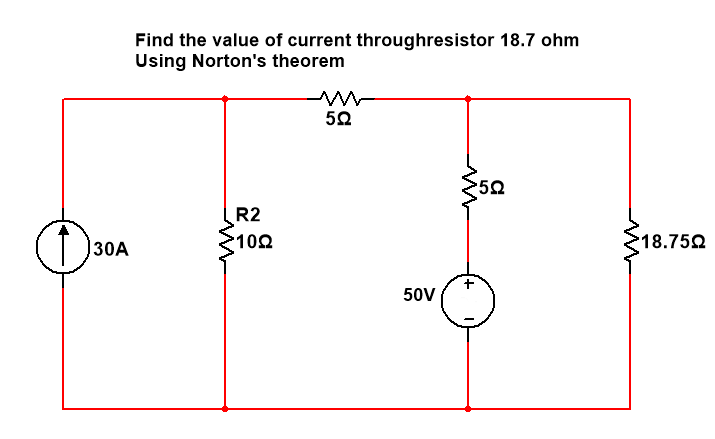
Q. 2 In the given network draw Norton’s equivalent circuit and find the current through 18.75Ω resistor.
Solution.–
Step 1-Short circuit the load resistance (RL)
Step 2-Calculate the short circuit current IN or ISC.
I1=30A
I3= ISC or IN
(in mesh 2) -10I1+20I2-5I3=-50 ————eq.1
-10*30+20I2-5I3=-50
20I2-5I3=250
(In mesh 3) -5I2+5I3=50 ———-eq. 2
by solving eq 1 & eq 2
I2=20A
I3=30A
I3=IN=30A
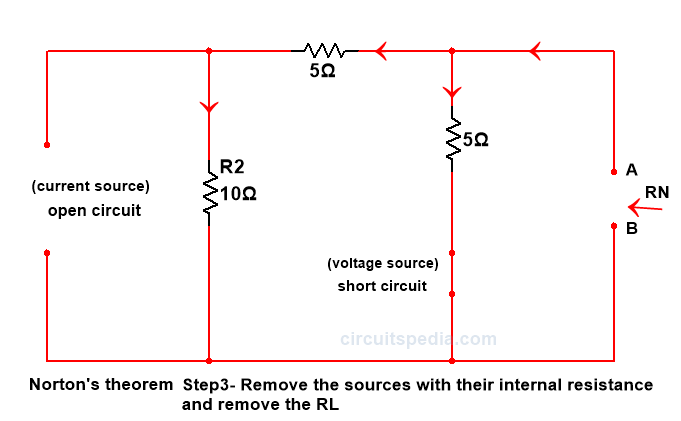
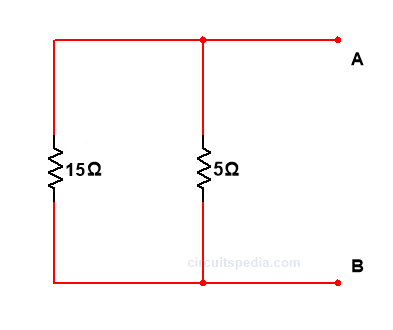
Step 3.-Remove all sources with internal resistance and Remove Load resistance RL
RN=15*5/15+5 = 3.75
Step 4.-Draw Norton equivalent circuit and calculate the IL using Identity IL=IN.RN/RN+RL
30*3.75/3.75+18.75=5A
S0, IL=5A (Ans)
FAQ(Frequently asked questions) – Norton’s Theorem
Q: What is Norton’s Theorem?
A: Norton’s Theorem is a technique in electrical circuit analysis that simplifies complex circuits containing multiple sources and resistors into an equivalent current source and resistor. It allows for easier analysis and calculations of circuit behavior.
Q: What is the difference between Norton’s Theorem and Thevenin’s Theorem?
A: Norton’s Theorem and Thevenin’s Theorem are similar in that they both simplify complex circuits, but they differ in the equivalent circuit representation. Norton’s Theorem replaces the original circuit with an equivalent current source and resistor, while Thevenin’s Theorem replaces it with an equivalent voltage source and resistor.
Q: What is the Norton equivalent circuit?
A: The Norton equivalent circuit consists of an equivalent current source, called the Norton current (In), in parallel with an equivalent resistance, called the Norton resistance (Rn). This equivalent circuit accurately represents the original circuit in terms of current behavior.
Q: How is the Norton current (In) determined?
A: The Norton current (In) is determined by calculating the short-circuit current across the two terminals of the original circuit. It represents the current that would flow through a short circuit if the original circuit were connected across those terminals.
Q: How is the Norton resistance (Rn) calculated?
A: The Norton resistance (Rn) is calculated by finding the equivalent resistance seen from the terminals of the original circuit when all the independent sources are turned off (replaced with their internal resistances). This can be done using various circuit analysis techniques, such as mesh analysis or nodal analysis.
Q: What are the benefits of using Norton’s Theorem?
A: Norton’s Theorem provides several benefits, including:
- Simplification: It simplifies complex circuits into a single current source and resistor, making analysis and calculations easier.
- Circuit optimization: It helps identify the optimal load resistance that maximizes power transfer from the source to the load.
- Circuit design: It facilitates circuit design by allowing designers to replace a complex circuit with a simpler equivalent circuit without altering the circuit’s behavior.
Q: When is Norton’s Theorem most useful?
A: Norton’s Theorem is most useful when analyzing circuits with multiple sources and resistors, especially when the behavior of the circuit in terms of current flow is of primary interest. It simplifies the circuit into an equivalent current source and resistance, making calculations and analysis more manageable.
Q: Can Norton’s Theorem be applied to circuits with reactive components?
A: Yes, Norton’s Theorem can be applied to circuits with reactive components, such as capacitors and inductors. The reactive components are considered in the calculations of the Norton resistance, taking into account their impedance at the frequency of interest.
Q: Can Norton’s Theorem be used for circuits with nonlinear elements?
A: No, Norton’s Theorem is not applicable to circuits with nonlinear elements, such as diodes or transistors. It is primarily used for linear circuits with resistive elements.
Q: Can Norton’s Theorem be used for AC circuits?
A: Yes, Norton’s Theorem can be applied to AC circuits by considering the AC impedance of reactive components. The Norton current and resistance are determined based on the AC behavior of the circuit at the frequency of interest.
————————————————————–
Click here for Electronics MCQ quiz
Also read
-
Thevenin theorem
-
Kirchoff’s law (KCL, KVL)
-
Logic gates
-
Zener diode working
-
What is Opto-coupler/Opto-isolator

