Optocoupler/Optoisolator
what is optocoupler
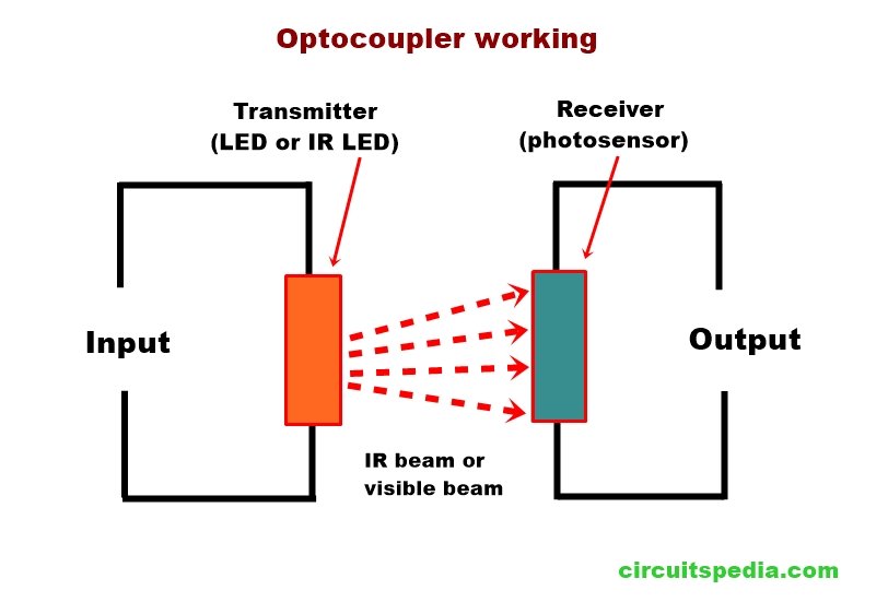
Opto-coupler is an electronic component that is used to conduct the electrical signals from one circuit to another circuit without directly being connected between them. In other words, an optocoupler is used to transfer electrical signals between two circuits optically. Here both circuit is electrically isolated from each other. Opto-coupler is also called photocoupler, optoisolator or optical isolator. An optocoupler is mainly used to prevent an electrical collision by isolating the circuit. This is also used to eliminate unwanted noises.
working principle of Optocoupler
An optocoupler consists of a Transmitter as an IR LED and a Receiver as a photosensitive component. when light is emitted by an LED and that light hits the photosensor (Photodiode, Phototransistor, PhotoTriac) then the photosensor starts to flow the current. in this system, the Input Light is proportional to the current at the output.
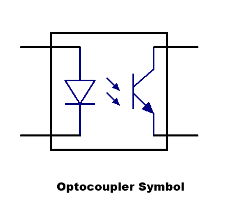
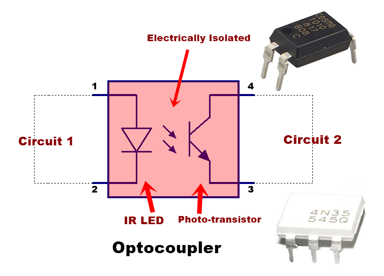
This is the internal circuit mechanism of an optocoupler. The left side is a led connected through pin 1 and pin 2. And the right side is a phototransistor, this phototransistor is sensitive to light. When the power is given to led, the led emits the light and that light falls on the BASE of the phototransistor, After falling on the base of the phototransistor this will activate and the output circuit connected with the transistor can be controlled. Here the input circuit is connected only with the LED pins of the optocoupler, Output circuit is connected to the phototransistor. Both input and output circuits is fully Electrically isolated.
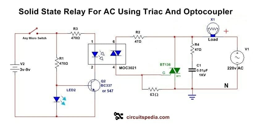
There is non-conductive material and space is transparent between LED and Photo-transistor. The electrical isolation is very high generally 10KV or higher. Opto-Triac (photo-Triac) is also used at the place of the Photo-transistor in the optocoupler for direct AC supply control at the output.
Optoucpler IC uses an LED optically coupled to a phototransistor, photodiode, or Photo TRIAC in a single package
The optocoupler is commonly used where A computer system or any digital system needs to control or drive a motor or control the high voltage devices. Here computer system circuit and Motor controlling device is fully electrically isolated, and there is no interference of electrical signal.
If we need to connect a 220v AC Motor that is controlled by a microcontroller or Arduino etc. In this case, we cannot directly connect both. Then there is optocoupler is used. Microcontroller output is directly connected with the input of LED of the optocoupler, and the Phototransistor is connected with the output component like Relay or Triac for 220v AC connection with the Motor.
In SMPS or any power supply circuit optocoupler may be used to detect the varying DC sample voltage of output and give feedback to input to control the power supply with maintaining the complete electrical isolation between the input and output circuit.
Saturation and linear Mode operation of the optocoupler
Saturation mode
In saturation mode LED will be ON or OFF so, the output transistor is fully off or fully ON, which means conducting or non-conducting mode. This mode is used where needed to protect the microcontroller pins from the high voltage of the output circuit. For example in a motor drive using a microcontroller, the motor needs high current and high voltage. The motor will be ON or OFF completely in this mode.
Linear mode
In this mode, LED will get a pulse of signal with a variation. The illumination of LED is varied or controlled with a sample of voltage or signal, then the phototransistor also provides variable conduction to the output. This can be used in a switched-mode power supply (SMPS) or controlling different circuitry where error detection at the output is required.
Photodiode vs Phototransistor optocouplers
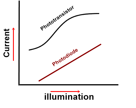
Photodiode optocouplers are better than phototransistor optocouplers in a linear relationship between the current and the light. Although phototransistor optocoupler can pass the analog audio signals at wide frequencies by varying the LED beam that goes to the BASE of the phototransistor. The transistor output varies to amplify as the light beam gets on its BASE. But some distortion may occur at high frequencies.
Input light and output current relationship of the photodiode optocoupler is good in most audio and some digital signals even though the output signal amplitude of the photodiode is very less than output provided by the phototransistor.
Why use optocouplers in electronics?
There are various types of circuits in digital communication systems, power supply systems,s, and other hardware systems designed using optocouplers by engineers because it make high sensitivity, for protection, most convenient fast switching and are highly responsive with a digital signal, etc.
Applications of optocouplers
There are the following main uses of the optocoupler
Allow you to use small digital signals to control larger AC voltages.- Solid State Relay is the best example of this. In this, you can switch ON or Switch OFF A 220V AC Load by using 5V DC-operated signal supply.
- Electrical Isolation: One of the primary uses of optocouplers is to provide electrical isolation between two parts of a circuit. This isolation prevents high voltages or transients in one part of the circuit from affecting the other part, thus protecting sensitive components and ensuring safe operation.
If you need to drive a high-voltage motor using the command with a microcontroller then the optocoupler will provide a switching system with a full electrically isolated connection between the motor and microcontroller output.
- Signal Transmission: Optocouplers are often used to transmit signals between different parts of a circuit without a direct electrical connection. This is particularly useful in noisy environments or where there is a risk of ground loops, as optical signals are immune to electromagnetic interference (EMI).
- Voltage Level Shifting: Optocouplers can be used to shift voltage levels between different circuits. For example, they can interface between low-voltage logic circuits (such as 3.3V or 5V) and higher-voltage circuits (such as 12V or 24V), ensuring compatibility without direct electrical connection.
- Galvanic Isolation: In systems where galvanic isolation (no direct electrical connection) is required for safety or regulatory reasons, optocouplers provide an effective solution. They separate circuits electrically while allowing data or control signals to pass optically.
- Noise Reduction: Optocouplers can help reduce noise and crosstalk between different parts of a circuit by breaking the electrical connection that could otherwise carry noise currents.
- Switching and Control: Optocouplers are commonly used in switching applications to control power transistors, relays, or other switching devices. The input side (LED) can be driven by a low-power signal, while the output side (phototransistor or photo-diode) can control a higher power load.
- Feedback Circuits: They are used in feedback loops where isolation between the input and output is necessary to prevent feedback oscillations or stability issues.
- Safety and Protection:
1. Protection from the highly sensitive circuit from a high voltage circuit –They play a crucial role in the safety circuits of electronic devices by isolating potentially hazardous voltages or currents from user-accessible parts, thereby preventing electrical shock or damage. If you need to drive a high-voltage motor using the command with a microcontroller then the optocoupler will provide a switching system with a full electrically isolated connection between the motor and microcontroller output.
2. Protection from high voltage spikes – The optocoupler is also used as a fuse with more advanced features than a fuse. In a circuit, an optocoupler is used to switch a system using a digital signal or using a very low voltage, but if there is spikes of voltage or surge current occurs then the whole output circuit will be non-affected because the optocoupler gets damaged only, and stops the passes the current to next portion.
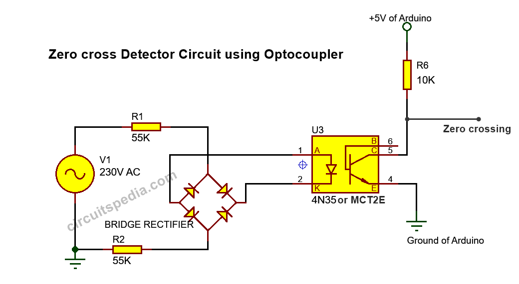
- Using optocouplers for sensing zero crossing of AC sources– by the response time is very fast (nanoseconds), On and off very fastly of the optocoupler, it is widely used to detect the zero-cross of ac power mains by using a rectifier. and by using this digital signal can be found for waveform changing as we required.
Also uses to Remove electrical noise from signals.
—————————————————————–
Some Most Using and Popular Optocoupler ICs are -PC817, 4N35, MOC3021 etc.
FAQ(Frequently asked questions) – Optocoupler
Q: What is an optocoupler?
A: An optocoupler, also known as an optoisolator, is an electronic component that combines an LED (light-emitting diode) and a photodetector, typically a phototransistor or a photodiode, within a single package. It provides electrical isolation between input and output circuits by using light to transmit signals.
Q: How does an optocoupler work?
A: An optocoupler works by converting an electrical signal on the input side into light using the LED. This light then illuminates the photodetector on the output side, generating a corresponding electrical signal. The input and output circuits are electrically isolated, and the signal transfer occurs through the light.
Q: What is the purpose of using an optocoupler?
A: Optocouplers are primarily used for electrical isolation and noise reduction in electronic circuits. They provide protection against voltage spikes, electrical noise, and ground loop issues, and help prevent interference between different parts of a system.
Q: What are the main components of an optocoupler?
A: The main components of an optocoupler include an LED (input side) that emits light when current flows through it, and a photodetector (output side) that converts the received light into an electrical signal. The photodetector can be a phototransistor, a photodiode, or other light-sensitive devices.
Q: What are the advantages of using optocouplers?
A: Optocouplers offer several advantages, including electrical isolation between input and output circuits, protection against voltage spikes and noise, low power consumption, high reliability, wide operating temperature range, and compatibility with digital and analog signals.
Q: What are the applications of optocouplers?
A: Optocouplers find applications in various fields, such as:
- Isolation of high-voltage and low-voltage circuits in power supplies and motor control circuits.
- Signal isolation and noise reduction in data communication systems.
- Protection of sensitive components from high-voltage or noisy environments.
- Feedback control and signal conditioning in industrial automation and instrumentation.
- Isolation and control of switches, relays, and solid-state devices.
Q: How do you select an appropriate optocoupler for a specific application?
A: When selecting an optocoupler, important factors to consider include the required voltage and current ratings, input and output compatibility, speed and response time, isolation voltage, temperature range, and any specific application requirements.
Q: Can optocouplers be used for both digital and analog signals?
A: Yes, optocouplers can be used for both digital and analog signals. They provide electrical isolation and signal transfer for various types of signals, including on-off digital signals, pulse signals, and continuous analog signals.
Q: What are some considerations for using optocouplers?
A: Some considerations when using optocouplers include proper drive current for the LED, ensuring sufficient insulation and clearance distances, considering temperature and aging effects, and understanding the optocoupler’s response time and bandwidth limitations.
Q: Can optocouplers fail over time?
A: Yes, optocouplers can experience degradation or failure over time due to factors such as LED aging, temperature stress, high voltage or current surges, and mechanical stress. Therefore, it is important to consider the optocoupler’s expected lifespan and any relevant datasheet specifications.
Also Read
-
How capacitor block dc current
-
Solid State Relay With Triac And Optocoupler
-
Automatic Light Activated Bulb Switch Controller
-
Zener diode working
-
How does a Relay Work
