Contents
Comparator
A comparator is a circuit that compares two input voltages or currents and gives output High or Low as per the input signal. The Output is a digital form according to the input signal compared with the reference. Basically, a comparator is used in electronics to compare the two Analog input signals given on both input terminals and we get the Digital output as High level or Low level.
A comparator is used to sense the signal of a predefined rich level. If I set a level to sense then I can use a comparator to sense it when the input signal of this level crosses more or below the level, suddenly the output is changed from Low to high and high to low. The comparators are used for so many electronics instrumentation for automation and drive different logic circuits.
Difference between operational amplifier (op-amp) and comparator
The symbol of the operational amplifier and comparator are looked the same. But Op-amp is designed to accept an analog input signal and also give the output Analog signal. But the Comparator accepts the analog input signals but gives the digital output. Comparators are faster than the operational amplifier. An op-amp will works as the comparator if using the transistor at the output.
If the input is applied at the + pin, this is called non-inverting input
If the input is applied at the – pin then this is called the inverting input.

1. Non-inverting mode
If I connect the input voltage at the non-inverting input and set a reference voltage level at inverting input which is to be sensing. In this circuit, the voltage will compare with the reference. If the applied voltage is lower than the reference voltage then the output is LOW, and if the applied input voltage is greater than the reference voltage then the output will be HIGH. Here High-level means output is directly connected automatically with VCC and Low means Output is directly connected with Ground.
For example, if we set the reference voltage at 6v, then when the input voltage increases to 6v then the output suddenly swings to HIGH and gives the voltage the same as VCC, Otherwise, output gives the LOW or 0v voltage.
Input voltage > Reference Voltage – Output HIGH
Input voltage < Reference Voltage – Output LOW
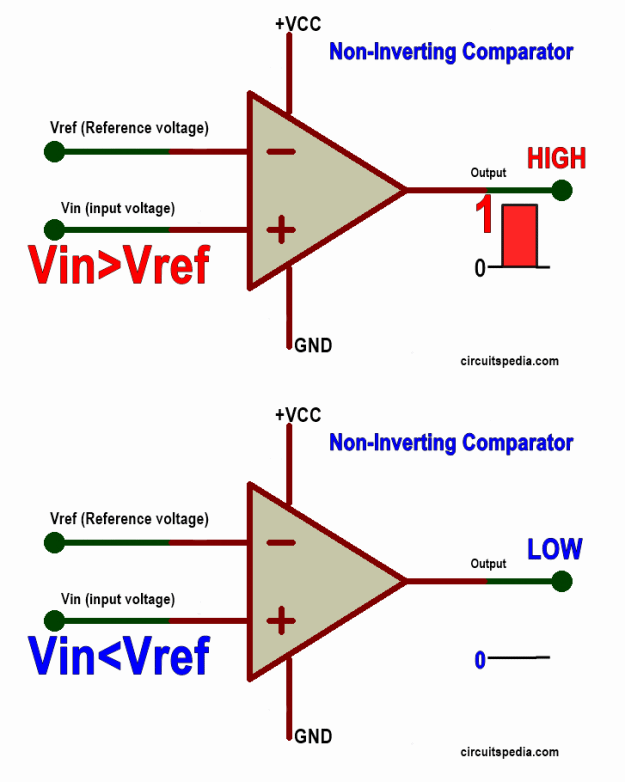 comparator circuit diagram
2. Inverting Comparator (Inverting Mode)
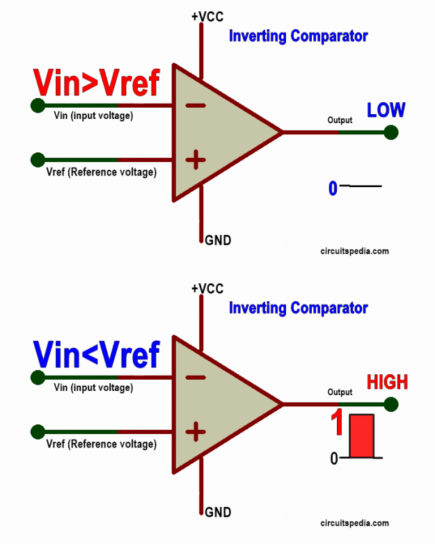
In inverting mode the input voltage is connected with the Inverting terminal and the reference voltage is st at the non-inverting terminal. In this connection, the voltage at the Inverting terminal will be sensed and compared with the voltage at the non-inverting terminal which is the reference voltage. The inverting mode comparator works reverse to the non-inverting comparator. This means If the voltage at Inverting terminal is greater than the Reference voltage then the output will be LOW, But If the Input voltage is Lower than the Reference voltage then the Output Will be HIGH. This comparator gives output Inverted of input.
For example, the Reference voltage is adjusted at 6v, when the input voltage increases and goes to 6v then the output will suddenly swing to LOW or 0v. Otherwise, the output will be HIGH and give the voltage the same as VCC.
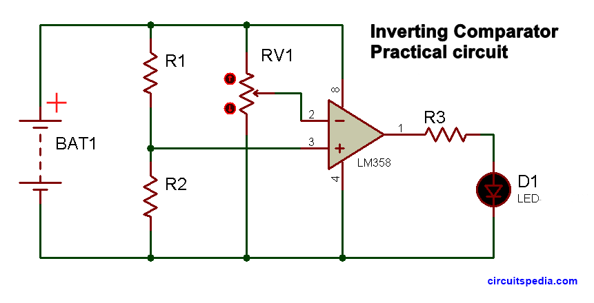
The LM358 is the very popular comparator ic used for general purposes. This ic has 2 opamp comparator. LM324 is also a very popular and most using comparator ic. It has quad op-amp comparator.
FAQ)Frequently asked questions)
Q: What is a comparator in electronics?
A: A comparator is an electronic device or circuit that compares two input voltages and produces an output based on the voltage relationship between them.
Q: How does a comparator differ from an operational amplifier (op-amp)?
A: Comparators and op-amps are similar in structure but have different internal circuitry. Comparators are designed to provide fast switching between output states based on voltage comparison, while op-amps are intended for amplification and are typically slower.
Q: What is the output of a comparator?
A: The output of a comparator is a digital signal that switches between two voltage levels, typically a high voltage (e.g., Vcc) and a low voltage (e.g., ground), depending on the comparison result.
Q: What are the typical applications of comparators?
A: Comparators are widely used in various applications such as voltage level detection, analog-to-digital converters, window detectors, overvoltage/undervoltage protection circuits, oscillators, pulse-width modulation (PWM), and more.
Q: Can comparators be used with single-supply voltage?
A: Yes, some comparators can be used with a single supply voltage by creating a virtual ground reference or using voltage dividers to bias the inputs appropriately.
Q: What are some important parameters to consider when selecting a comparator?
A: Key parameters include input offset voltage, input bias current, response time, supply voltage range, input and output voltage levels, open-drain/open-collector output configuration, and input and output impedance.
Q: What is the inverting mode of a comparator?
A: In the inverting mode, the input voltage is applied to the inverting (-) input of the comparator, while a reference voltage is connected to the non-inverting (+) input. The output of the comparator switches depending on whether the input voltage is lower or higher than the reference voltage.
Q: What is the non-inverting mode of a comparator?
A: In the non-inverting mode, the input voltage is applied to the non-inverting (+) input of the comparator, while the reference voltage is connected to the inverting (-) input. The output of the comparator switches depends on whether the input voltage is lower or higher than the reference voltage.
Q: What are the advantages of the inverting mode of a comparator?
A: The inverting mode provides a simple and straightforward configuration, and the output is inverted with respect to the input voltage. It is often used when an inverted output signal is desired.
Q: What are the advantages of the non-inverting mode of a comparator?
A: The non-inverting mode provides a non-inverted output signal that matches the input voltage polarity. It is commonly used when a non-inverted output is required or when the input signal has a high impedance.
Also read
-
What is Zener Diode
-
Operational amplifier (Op-amp)
-
LOGIC GATES
-
What is Opto-coupler/opto-Isolator
-
What is Active, Passive, Linear, Non-Linear, Bi-Lateral elements



Interesting article! I never knew that comparators were so versatile and widely used in electronics. The explanations and examples were clear and easy to understand. I will definitely keep this in mind for my own electronics projects.