Here I am presenting some Most using and popular automatic stabilizer circuit diagram.
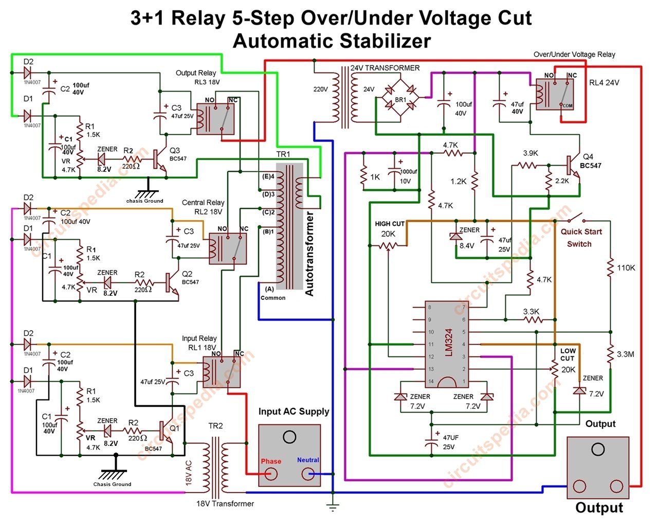
3 relay stabilizer circuit diagram
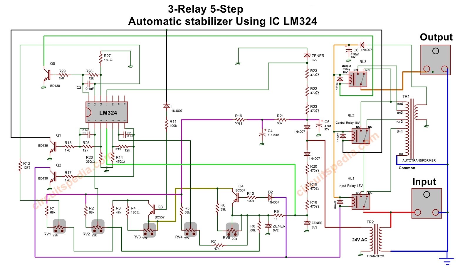
These are the following schematics diagrams of most using stabilizers. you can troubleshoot or construct a stabilizer by using the following circuit diagrams. this circuit diagram includes 2-relay, 3-relay with IC and without IC and with high voltage auto cut. All are diagrams of the automatic stabilizer.
All chassis ground is connected together and this is also connected with DC negative supply (DC ground).
This circuit uses a total of 4 relays and one LM324 op-amp comparator ic.
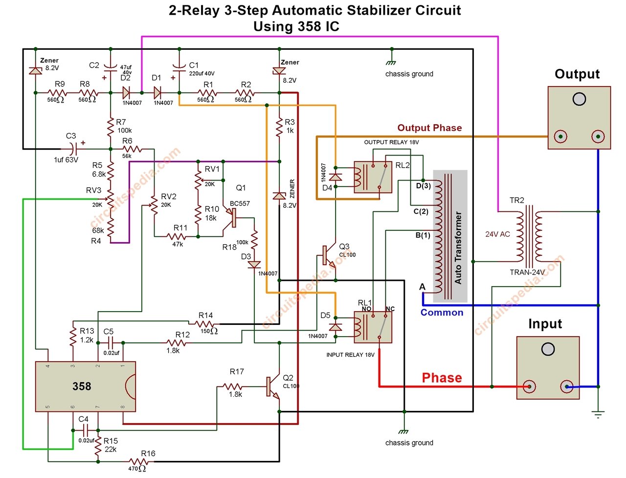
2 Relay automatic stabilizer circuit
This circuit was made using the one 358 comparator IC and 2 relays.
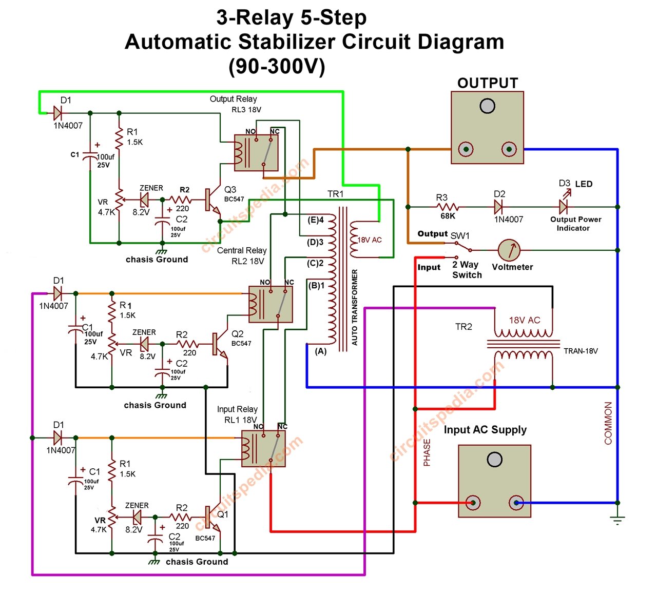
3 relay stabilizer circuit
This automatic stabilizer circuit is made using a total of 3 relay but there is no IC used .
Related Post
-
Dark Sensor Circuit
-
Light Activated Switch Without Relay
-
Delay ON Timer circuit using transistor
-
Clap ON OFF Switch Using 555 and 74LS74
-
Infrared proximity sensor circuit
-
LED Sequence Flashing | LED Flasher using 4017


The schematics of the above AC mains stabilizer circuits are wonderful. Keep up the good work.