Clap ON Clap OFF Switch circuit Diagram
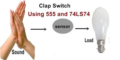
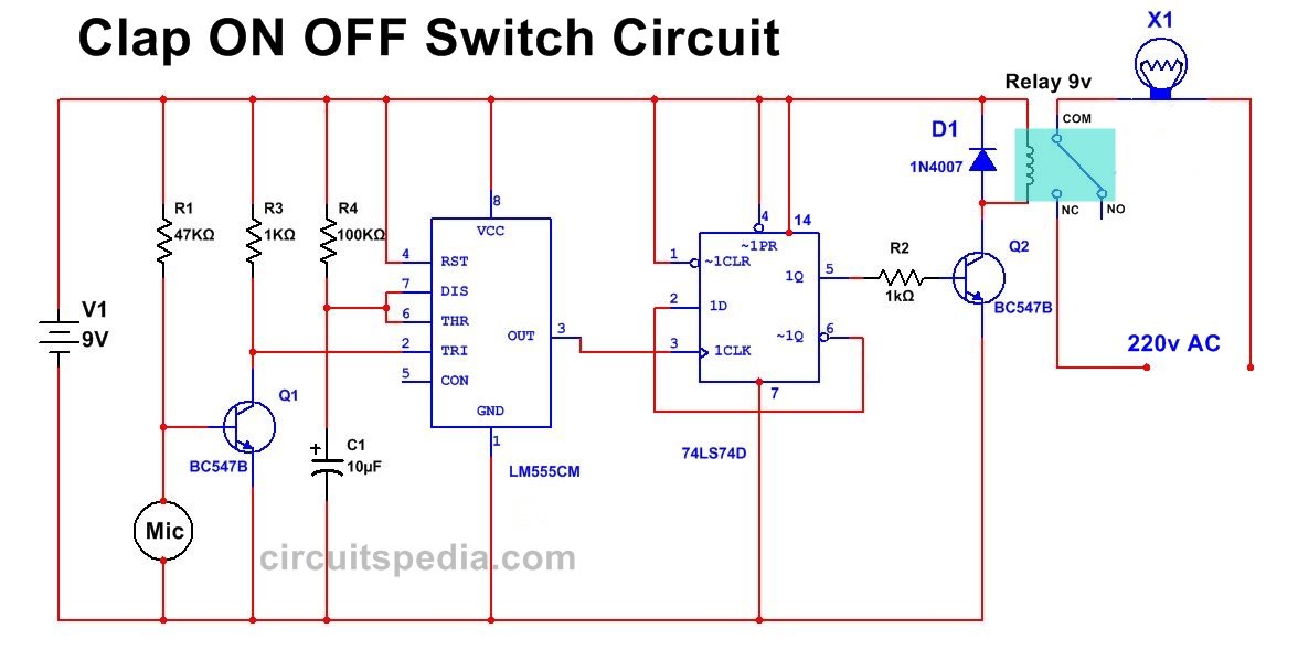
This is Another Clap ON-OFF Circuit Diagram Using 555 Timer and 7474 IC. When Clap the Load is Switch ON and When Again Clapped Then Load is Switch OFF. This Clap operated ON OFF Switch Circuit is Useful to ON-OFF any Appliance. The circuit is work By the Detection of clap sound. Clap Sound operated Switch circuit.
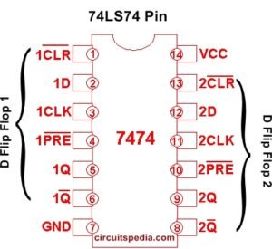
74LS74 ic is Dual D type flip flop. But in this circuit, Only One Flip Flop is used to the operation
This is ON OFF Switch by using Clap Sound. When You Clap The Load is Switch ON Again When Clap the Load is Switched OFF, It means this circuit Switch Any Appliance by Detecting the Sound. A condenser MIC is used to Sense the Clap sound. 
Connect the All Components As Circuit Diagram, use 9-12 v to operate the circuit. You can Make More Sensible the condenser mic by an External Metal case covering to catching Maximum sound.
clap switch circuit diagram
Components
IC
555 – 1
7474 – 1
Resistor-
47K- 1
1K- 2
100K-1
Transistors
BC547 – 2
Capacitors
10uf 25v – 1
Diode– 1N4007 -1
Relay 9v – 1
Condenser MIC-1
Must Read Clap ON OFF Switch Using Lm358 and 4017


1volt signel cercute dayagram
Some genuinely select articles on this site, saved to bookmarks .