op-amp based Over current /short circuit protection circuit
This is a short circuit and Overload protection circuit using op-amp LM358. This protection circuit can be used in any DC load to protect Overload and short-circuit. This is a very simple and also easy circuit for DC Load.
When Load is increased and cross the required level or if any short-circuit occurred in the portion of load, then the Load is automatically switched off until the again normal load.
Circuit diagram
 working
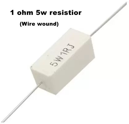
This circuit is used an op-amp ic LM358. In this circuit, the op-amp is used as a comparator. The NON-INVERTING input terminal is connected with A Potentiometer that is connected across +ve and Ground. A 5W Resistor of 1 OHM is connected between the Ground and MOSFET source, This resistor is used as a voltage drop detector for giving the signal to the comparator INVERTING input.
When the voltage at the Gate pin of MOSFET is high then the Load will get the supply and when the voltage at gate pin of MOSFET will LOW then the MOSFET will not give the supply to the load. and the GATE voltage depends on the output pin 1 of IC LM358. This means the MOSFET will ON and provide the supply to load If the only output of Comparator IC gives voltage to GATE. When the Load increased or Load starts to consume More current at the output then the current across the MOSFET and resistor R4 is also increased, as the current increases the voltage will also be increased across the resistor R4 (according to OHM’s law). And the voltage increased across the resistor R4, the voltage level at the inverting input terminal also increased and we know when the voltage at the inverting input is higher than non-inverting input then the output at pin 1 is LOW or 0V. So At the moment of overload the Load will automatically be switched off because of the output of the comparator will go to LOW and the Voltage at the GATE pin of MOSFET is zero, so MOSFET will not be activated. For example, if we use 1 Ampere load then the current across the resistor will be 1A and voltage should be across the resistor is 1V also (V=I.R). So we need to set the voltage at pin 3 of ic is higher than 1V (1.3 to 2V) by moving the potentiometer using a screwdriver and check the voltage using Multimeter on pin 3 with the ground. Adjust the voltage at pin 3 before use.
100K resistor connected as feedback to protect any fluctuation occurred by the comparator. 1M resistor is connected with MOSFET as PULL DOWN resistor to make MOSFET off unnecessary. Mosfet drain terminal is connected with Load negative terminal. IC 7809 is used to provide constant voltage to ic for the stable sensing operation.
Parts
LM358 Ic -1
Resistors
100K-1, 1Ω 5W – 1, 1M – 1
Potentiometer (variable resistor)- 50K -1
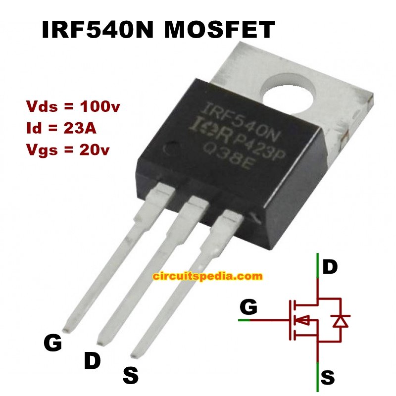
MOSFET – IRF540N-1
Regulator ic LM 7809 -1
Capacitor 100uf 25v -1
IRF540N MOSFET pin
7809 regulator ic Pin
Also read
- Fan Regulator/AC dimmer
- Short circuit auto cut relay switch for DC
- Siren Sound, Bird Sound, Tone generator using 555 timer
- Variable Current and voltage supply 1.5v-30v and 0-10A
- LOGIC GATES

