Contents
Variable voltage supply circuit 1.5v to 30v
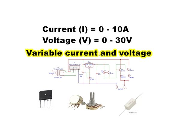
0-30V 0-10A regulated variable power supply circuit
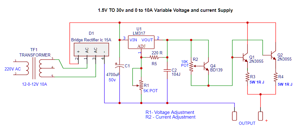
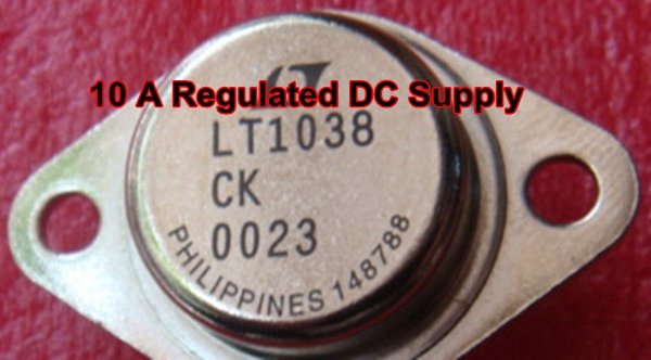
This is the circuit diagram of the voltage and current regulator circuit that can give the output of min 1.5v to max of 30v DC and current min 0 to max 10A. Use the 5k potentiometer for the adjustment of voltage and the 10k potentiometer with BD139 transistor for adjustment of current.
2 power Transistor 2N3055 is used in this circuit to control the output current. Use a Proper heat sink to fix both transistors because high current transistors get hot. Also use a heat sink with the LM317 ic.
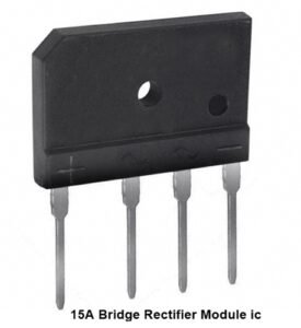
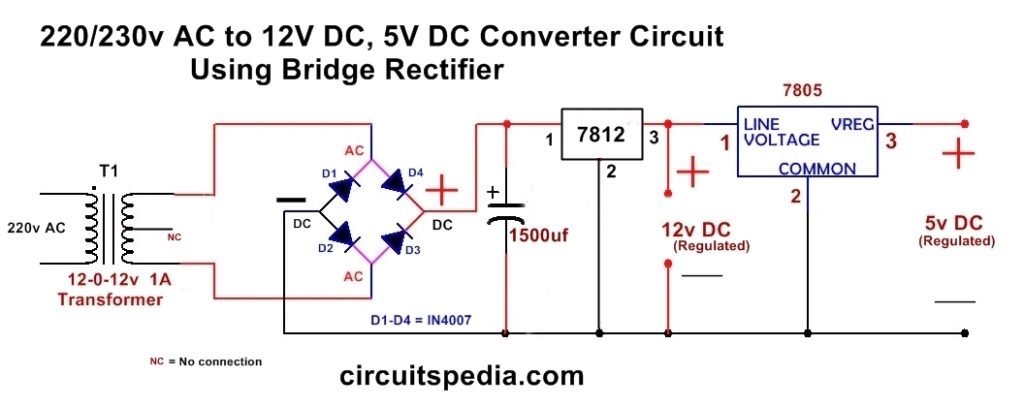
If you need a maximum of 5A current at output then use the 5A transformer. If you required 10A the use a 10A center taped transformer of 12-0-12v.Then output current depends on the current rating of the transformer. A transformer of 2 A will not give more than 2A current. connect the AC pins of the rectifier diode module with both side wires of the transformer of 12-0-12. The middle wire will no connected. The output of the transformer will provide about 24v Ac. The rectifier module IC is a readymade Bridge Rectifier.
Bridge rectifier ic module is available in the market of 15A or different current rating, you can use this rectifier module. Fix the circuit in a cabinet and both potentiometer knob connected with the circuit should out of the cabinet for adjustment.
Circuit diagram
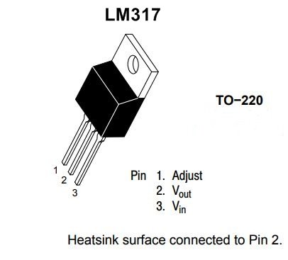
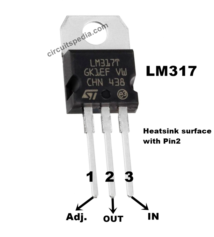
LM317 Regulator IC
The LM317T is an adjustable three-terminal positive-voltage regulator. This LM317 regulator IC capable of supplying more than 1.5 A over an output-voltage range of 1.25 V to 37 V. To set the output voltage it requires only two external resistors.
Here Resistors R1 and R5 set the output to any desired voltage over the adjustment range 1.2v to 37v. It has current limiting, thermal overload protection, and safe operating area protection. Overload protection remains functional even if the ADJUST terminal is disconnected. This device can also be used as a programmable output regulator, or by connecting a fixed resistor between the adjustment and output, the LM317 can be used as a precision current regulator.
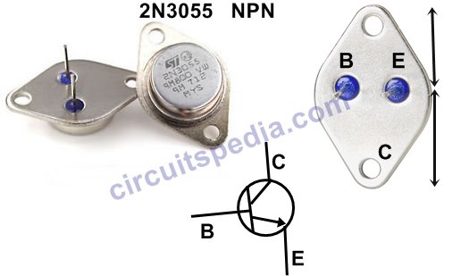
2N3055 Transistor
The 2N3055 transistor is a general-purpose NPN Power transistor built with a sealed metal case. This transistor is used for switching as well as amplifier applications.
- Maximum voltage across collector and emitter: 60V DC
- Maximum current allowed through collector: 15A DC
- Maximum voltage across base and emitter: 7V DC
- Maximum current allowed through base: 7A DC
- Maximum voltage across collector and base: 100V DC
- Operating temperature range: -65ºC to +200ºC
- Low collector-emitter saturation voltage
- Pb−free packages are available
- DC current gain (hFE) up to 70
- With hfe improved linearity
Components
Transformer 12-0-12 (10A) – 1
Bridge rectifier – 15A – 1
LM317 IC – 1
Capacitor 4700uf 50v – 1
Capacitor 104j 400v – 1
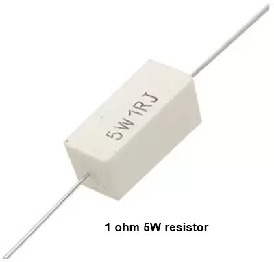
Resistor 220Ω (1/4W) – 1, 1Ω (5W) – 2
Potentiometer 5K-1 , 10K-1
Also read
-
Dark Sensor Circuit
-
How To Connect Microphone with Any Amplifier
-
How To Make A Blinking LED Circuit With 555
-
12v Battery Level Indicator With LM3914 ic
-
Simple LED Flasher Circuit with 555 timer

It’s actually a great and useful piece of info. I am satisfied that you
just shared this useful info with us. Please keep us informed
like this. Thank you for sharing.
Greetings! I’ve been reading your web site for a long time now and finally got the bravery to go ahead and give you
a shout out from Austin Texas! Just wanted to tell you
keep up the great work!