Contents
Electronic Fan Regulator
AC Light Dimmer circuit
Resistive fan regulator
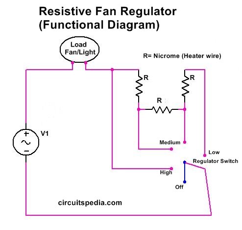
We first discuss the conventional big-size resistive fan regulator. Conventional Old ceiling fan regulators use resistive wire to connect in series and there are multiple points to connect the regulating knop switch to adjust the speed. This type of regulator works on a full resistor load between load and source to make a required disruption to current and voltage drop. A lower speed means higher resistance.
When setting the at low speed then the knob is going to flow current through the maximum Length of resistive wire. At medium, current flows by the middle point of the resistive wire, and at High speed there is no resistance means that the starting point of the resistive wire is connected with the fan supply.
These regulators need more space and look like a big rectangular box having a circular knob on it. These are also known as resistive regulators. The box consists of a wire wound resistor with different taps that are connected in series with the motor of the fan. Nichrome wire is used as resistive material in these, so a greater amount of power loss occurs by Heat produced through these resistive wires.
AC fan regulator circuit
The main advantage of this type of regulator is cheap, highly durable and no humming noise is produced in a fan at low speed.
Disadvantage – Even at low speed they consume the same power as high speed because resistive wire acts as a load in series with fan. Power loss is unnecessary by heat.
Electronic Fan regulator
There are basically two types of electronic fan regulators available in the market
- Triac based
- Capacitor based
Triac based Regulator/Dimmer
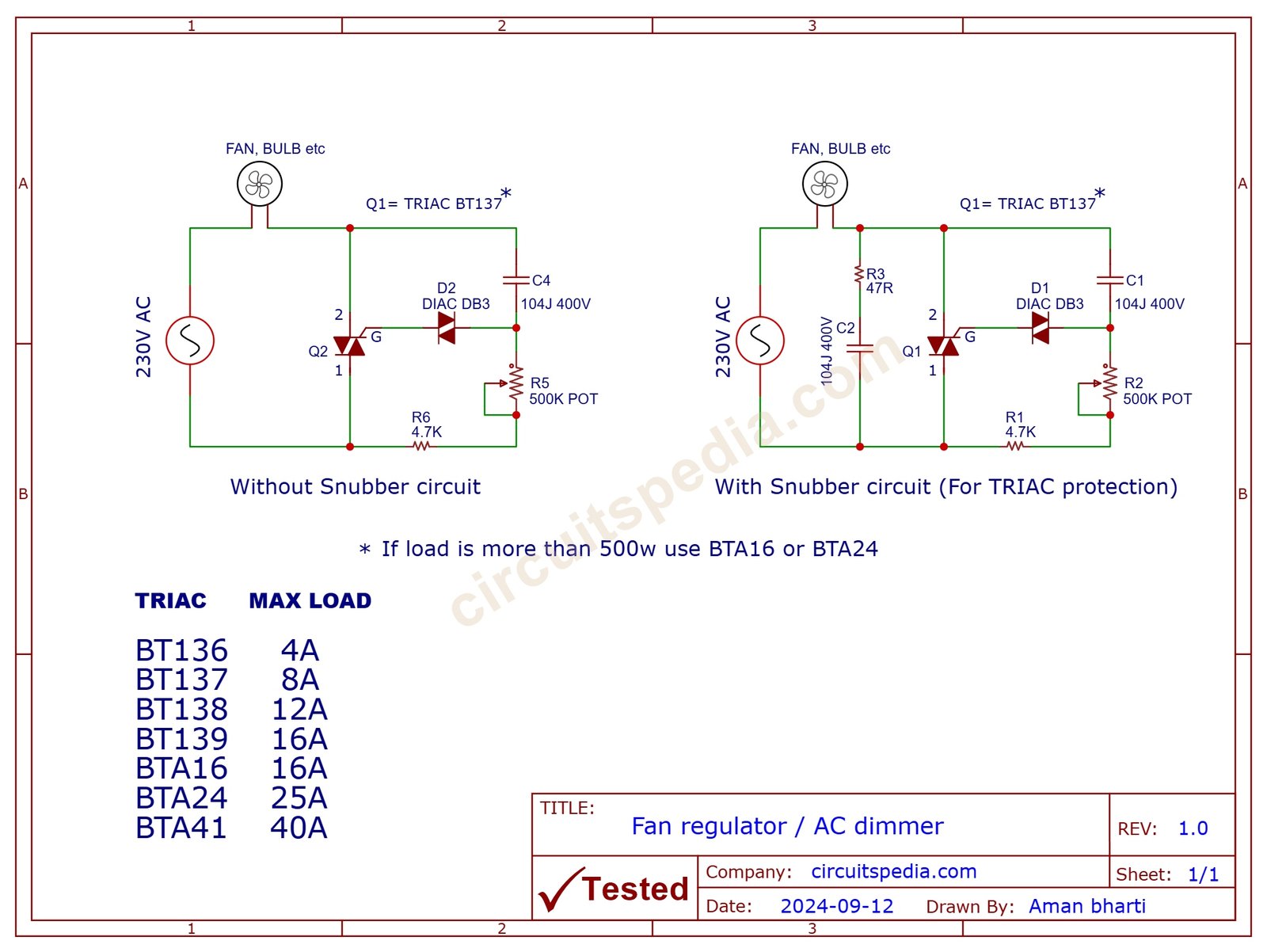
In the Triac-based electronic fan regulator circuit there are mainly three components used. Resistor, One Capacitor, One Diac, And One Triac. TRIAC is a semiconductor device belonging to the family of thyristors. This is directly used to control the speed by holding and releasing the current flow.
Working of Triac based Electronic fan regulator
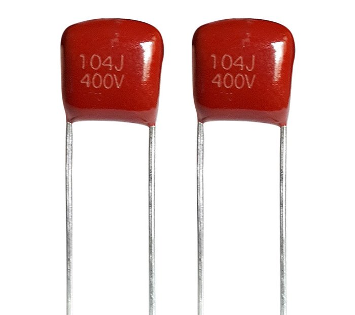
In this circuit, A Diac is connected with the gate terminal of the triac. One side of the Variable resistor connected to the Triac terminal through a 4.7k resistor and another side of VR connected to a capacitor is connected with Diac.
Also read- LED Chaser/Flasher circuit
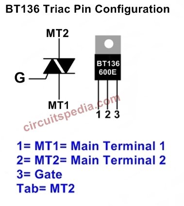
When the voltage across Diac crosses the level of VBO Then it gets triggered and it turned on. For DB3 The VBO is 32v (+/-4v). This means When the voltage across DB3 reaches 32v then it turns on and the current will flow through it. Diac is made by the combination of two diodes in an alternative direction, Two diodes are combined in opposite to each. Diac provides the gate signal of Triac and according to the gate signal, it passes the supply from MT2 to MT1.
The resistor and Capacitor make an R-C circuit to provide timing delay and timing constant for Diac input and then by the timing constant pulses it is able to create Limited voltage through triac and Load gets regulated input supply.
Diac gives full DC output for both negative and positive cycles, this is used for the triggering of Triac.
220v AC Fan regulator circuit
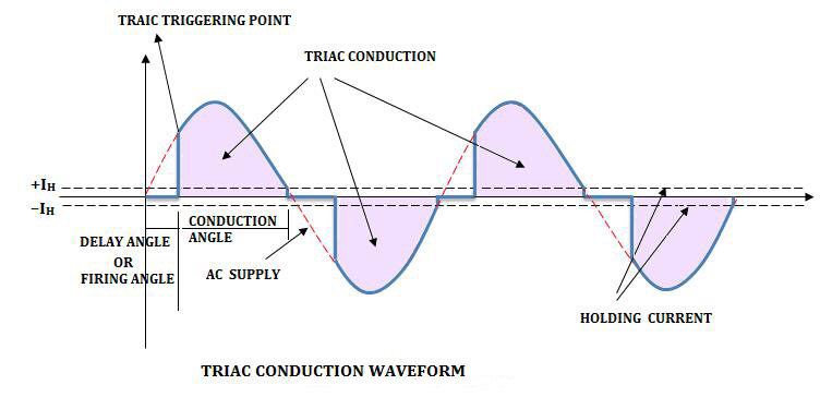
At first, when the supply is on, the triac is in an Off state, the capacitor gets a signal voltage through the Fan and resistor, and this capacitor is charged. When the capacitor is fully charged, the capacitor stores power, and Diac gets turned On Triac also turns on and the supply passes through Triac. As Triac turns ON Capacitor is Discharged. Again Capacitor gets current through the resistor bypassing the Load and input line and is Charged. The capacitor is Discharged by giving the power to Diac and therefore again Triac turns on because Diac gives a signal to the gate terminal.
This Charging and Discharging of the capacitor randomly occur and Triac turns ON-OFF Randomly also. The Timing Rate of charging of the capacitor is increased by the increase of the resistor value. So, the combination of the Resistor and capacitor in this circuit makes a timing delay.
Snubber circuit
A Protection circuit can be included for Triac protection by adding of the resistor and a capacitor in series with the parallel of Triac. This is called the Snubber circuit, an electrical circuit used to suppress (snub) voltage spikes and transients in power electronics. These voltage spikes are typically generated when switching devices are turned off, such as transistors or thyristors. This circuit protect the switching components from failure.
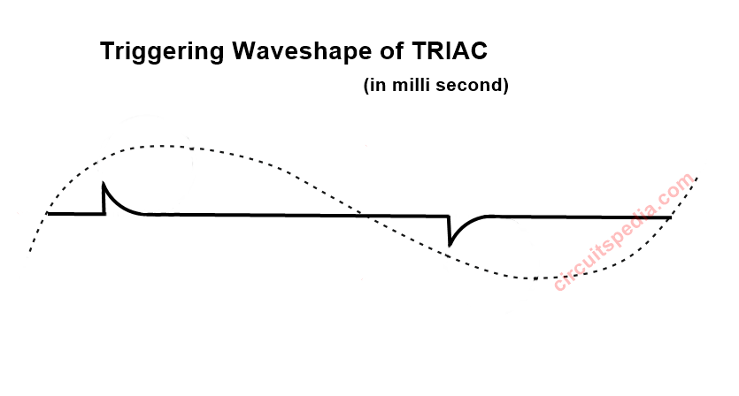
When we increase the timing of the charging rate of the capacitor then triac gets a delayed gate signal and it gives less voltage supply to the Load.
Advantage – Low Power consumption at a Low-speed Level. Cheap and Smaller Size
Disadvantage – A noise sound like a humm is produced by FAN when Low speed.
Capacitor based (Noiseless fan regulator)
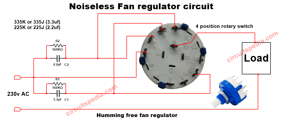
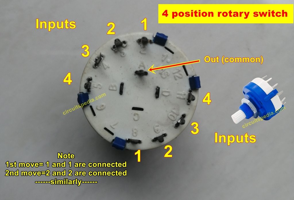
In the capacitive Regulator, there are some capacitors connected in series with the load and each capacitor has a resistor in parallel. Capacitive Regulator is very popular and easily available in the market. This is some costly than the triac-based regulator. But the result is better than the Triac regulator.
The advantage of this regulator is there is no noise humm sound produced by FAN. At Low-speed low power consumption.
VIDEO
Also read-
-
12v battery charger with an auto cut on full
-
Over-Voltage Automatic Switch off Circuit
-
LED Power indicator for 220v AC mains
-
Best Low power Mic Amplifier circuit using LM386
-
Solid State Relay With Triac And Optocoupler
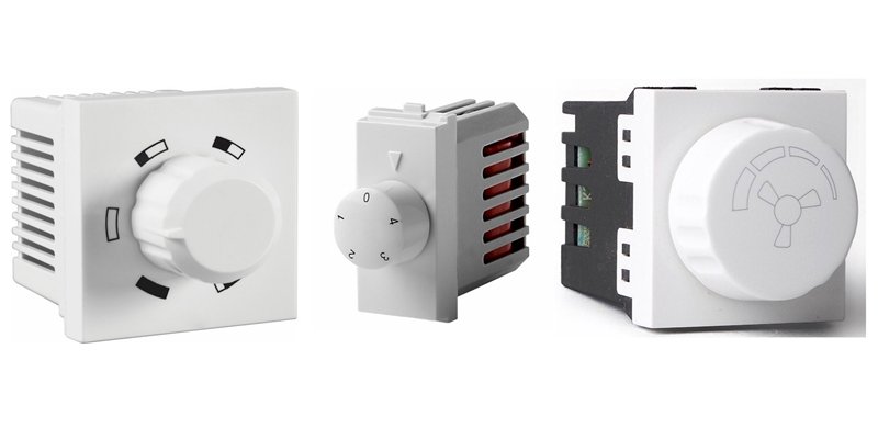
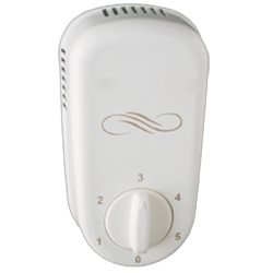


is this circuit diagram accurate? if i build, will it work just fine?
yes, you can build
Thank you. can you advise the wattage of resistors?
Nice expectation bro…
Very good analysis with pros and cons
Thanks….
Hello Aman,
Nice explanation…
But can we connect two Capacitor based step type regulators in series? I want more control over the fan speed than what is possible with those 5 steps. Technically this way we should get 20 steps if we connect two 5 step in series. But some steps will be redundant; so we might get 10 usable steps this way.
Very nice presentation
what is the wattage capacity is the capacitors ac dimmer
Depend on TRIAC. If you use TRIAC BT137 then can load upto 600W easily.
RC type Fan regulator is the best choice though there is some heat generation but still very best option.
Pingback: Iotics Technology Touch Switch Panel Teardown