Automatic Door Security Alarm System
Introduction
This is used to any Door or Gate to Detect Any human person or any animal pass across the gate. When Any Crosses the gate then Automatic alarm beeped for some duration and then after automatically stopped. So even any person or gateman or guard is not available at door, no can be entered through the gate separately. This is an IR based Security Alarm.
This circuit can be used at any door at there are no gatekeepers or any guard available. This circuit Detects any entry through Gate by using the method of interruption or obstruction of Light. The light of the infrared LED is not visible by the human eye so this operation is invisible.
Construction
IR LED is placed at one side of the gate and in the straight way of this LED a Photodiode is placed in this front as the light directly incident on the photodiode.
• Use 2 or More IR LED with separate Resistor on each in Parallel For More Range.
• Photodiode should be Covered With Black Tape Or Any Nontransparent Material, Because Photodiode Detects Environmental IR Rays Which Emitted From Sun and Then May be Malfunction. Sun is The Largest IR Emitter.
This is the circuit diagram of Gate Security Alarm.
click on image
When any person Want to cross the door then light incident broke through the person and then buzzer beeped for a duration of some seconds or minute. The duration of buzzer sound can be adjusted.
Here 555 timer IC is connected in MONOSTABLE mode and which duration of output is set for a fixed time.
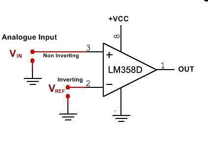
Here A comparator IC 358 is used. Non-inverting (PIN3) of voltage comparator is connected to the Photodiode and inverting (PIN 2) of voltage comparator is connected to a variable resistor of 10k. The output of the voltage comparator (PIN1) is fed to the Trigger pin of 555 timer. 555 Timer is configured in monostable mode here.
Working
Here IC LM358 Uses as the comparator. A comparator circuit compares two voltages and outputs either a 1 (the voltage at the – (negative) or a 0 (the voltage at the + side) to indicate which is larger. The Op-amp comparator compares one analog voltage level with another analog voltage level, or reference voltage ( VREF ) and produces an output signal based on this voltage comparison. In other words, the op-amp voltage comparator compares the magnitudes of two voltage inputs and determines which is the largest of the two.
Comparators are often used to check whether an input has reached some predetermined value. In most cases, a comparator is implemented using a dedicated comparator IC, but op-amps may be used as an alternative. Comparator diagrams and op-amp diagrams use the same symbols.
When the radiation of IR LED is falling on Photodiode, the voltage at the Non-Inverting Pin 3 (+) of voltage comparator is higher than the inverting Pin(-) and the output of the comparator is HIGH. The output of the comparator is connected to the trigger PIN (pin2) of the 555 timer, When output(pin1) of the Comparator is high, Trigger pin 2 is high. When Voltage at the trigger Pin of 555 is HIGH then the Its output is low.
So during the period when the IR rays fall on Photodiode, the 555 timer output remains LOW. when there is some movement, the falling of IR rays on the Photodiode gets interrupted and the voltage at the inverting end (Threshold voltage) of the voltage comparator becomes higher than the non-inverting end, for some moment. This makes the output of the comparator LOW and also makes the Trigger PIN 2 of 555 timer LOW. This will trigger the 555 timer, and the 555 timer’s OUTPUT goes HIGH and Buzzer beeps for a short duration. The duration of the beep can be increased by changing the value of resistor R1 or capacitor C1 (RC network in monostable mode of.
Inverting Means -ve
Non-Inverting Means +ve
- The sensitivity of the sensor can be changed by the variable resistor RV1.
- AC Light or alarm can be used in place of Buzzer, by using Relay. (the circuit is given in diagram under optional block)
- IR LED and Photodiode must be fixed in straightway to IR rays that can directly fall on the photodiode.
Demo Video of this Project
Must Read Audio Amplifier Circuit
Components-
IC
LM358(Comparator)-1
LM555(Timer)-1
Resistor
10K-1
100Ω-2
100K-1
VR-10K-1
Buzzer(5v)-1
Relay(5v)-1
Diode(1N4007)-1
IR LED-1
PHOTODIODE-1
Capacitor(10uf 16v)-1
Also Read DC Fan Speed controller Regulator circuit


