IR Based High sensitive Door Security Alarm circuit diagram
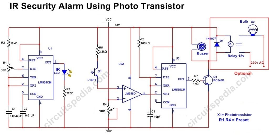
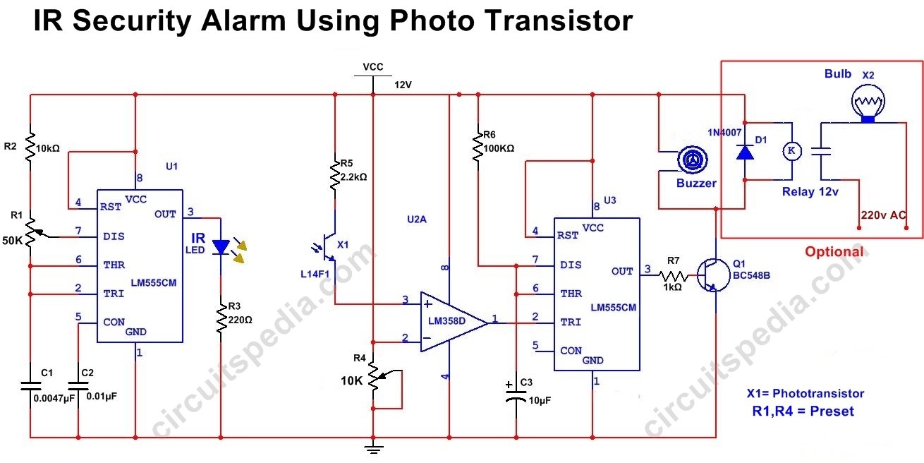
This IR based security Alarm circuit is highly sensitive. Here A Phototransistor L14F1 is used for the detection of IR rays.
555 timer ic is used to provide a pulsed output For Emitting of IR rays at specific Frequency. The first part of the IR Security Alarm circuit including 555 ic and IR LED. This section transmits A Specific Frequency For IR LED.
Next stage of a circuit including a comparator ic 358. The Phototransistor is connected with a non inverting input of this ic. The base pin of the Phototransistor is not connected with the circuit. The output of ic 358 is directly connected with the other 555 timer ic which is arranged in Monostable mode to give an output to Buzzer for fixed duration.
working Principle
When light falls on-base junction of phototransistor then it produces an inverse current and voltage between base and emitter, so at first, when there is no interruption between IR LED and Photo-transistor, the IR light falls on that. Then The voltage at the non-inverting pin of the comparator is smaller than inverting input (LOW). And if the voltage at non-inverting(Pin3) is Low than the inverting the Output of its at pin 1 is HIGH (+vcc).
When any Interruption occurs between IR LED and Phototransistor then the voltage at pin no 3 which is higher than the inverting input voltage, at this condition the output At Pin 1 is LOW (-VCC). This LOW voltage Trigger the 555 ic (u3). And after triggering this ic the output at pin 3 of 555 is HIGH. Here High Output is for a fixed duration because of Monostable connection is connected.
This HIGH output of 555 (u3) Turns on the Transistor Q1. After transistor activating, it Switches on the connected Buzzer. You can connect Light with the use of relay with the transistor.
Components
IC
LM358 – 1
555 – 2
Phototransistor L14F1- 1
Resistor
10K-1, 220Ω- 1, 2.2k-1, 100k- 1, 1k- 1,
Preset
50k -1, 10k -1
Transistor
BC548 – 1
Capacitor
0.01uf-1, 10uf-1, 0.0047uf-1
IR LED-1
Buzzer – 1 (12v)
Relay– 1 (12v)
Diode 1N4007-1


