Contents [hide]
All About Resistor
Introduction.
What is a Resistor
A resistor is the most common passive two-terminal component used in the electronics circuit. This device used in various circuits. Without a resistor, we can’t imagine any circuit. The resistor is a very important device to make a circuit. Any simple to the simple circuit we can see made using a resistor.
Working Of Resistor
The main function of the resistor is to limit the flow of current. It restricts and controls the power supply between other components. Controlling of supply through the path because it makes a disturbance inflow of electrons. The resistance of any resistor is noted by ohm (Ω), ohm (symbol of ohm is omega) is a unit of measurement of resistance of any resistor. If a resistor has a large value of resistance then it creates more disturbance to the flow of electrons. It means large value resistors have large resistance and a small value resistor creates very little disturbance and it has a small resistance.
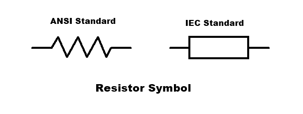
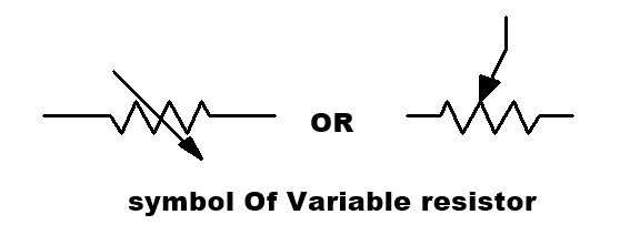
Symbol.
Types of Resistors
-
Fixed resistors:
This type of resistor has a fixed value. They are used in electronics circuits where does not require to change in the value of resistance. This sets fixed conditions in a circuit. The values of these resistors are determined during the designing of the circuit, and they should never need to be changed to “adjust” the circuit.
Fixed resistor types
There are mainly 6 types of fixed resistor:
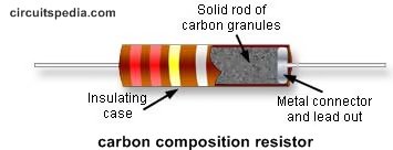
Carbon composition:
They are formed by mixing of carbon granules with a binder which was then made into a small rod. This type of resistor was large by today’s standards and suffered from a large negative temperature coefficient. The resistors also suffered from large and erratic irreversible changes in resistance as a result of heat or age. In addition to this, the granular nature of the carbon and binder leads to high levels of noise being generated when current flowed.
Carbon film:
The carbon film resistor is formed using a ceramic carrier rod onto which a thin layer of pure carbon is deposited as a film. It is the thin carbon film that acts as the resistive element. To enable the carbon film resistor to have the correct resistance, a helical cut is normally made into the film. This increases the length of the path and also reduces the width of the resistive element.
This type of resistor is formed by “cracking” a hydrocarbon onto a ceramic former and then deposited film had its resistance set by cutting a helix into the film. These resistors are used in many RF applications. They exhibited a temperature coefficient of between -100 and -900 ppm / °Celcius. The carbon film is protected by a conformal epoxy coating or a ceramic tube. 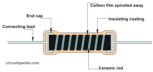 The carbon film resistor provides better performance in many respects than the carbon compositing resistor, but this resistor type was overtaken by metal oxide film and metal film resistors which gave even better levels of performance.
Metal oxide film:
This resistor uses a metal oxide film deposited on a ceramic rod. Metals oxide such as tin oxide is deposited onto the ceramic rod. This type of resistor has a temperature coefficient of around ±15 parts per million / °K, giving it a far superior performance to that of any carbon-based resistor. This type of resistor is now one of the most widely used forms of resistor along with the metal film type rather than using a carbon film. The resistance of the component is adjusted in two ways. First, the thickness of the deposited layer is controlled during the initial manufacturing stages. Then it can be more accurately adjusted by cutting a helical groove in the film. Again the film is protected using a conformal epoxy coating. The noise level of these resistors has lower than the carbon film resistor. This type of resistor can be supplied with a much closer tolerance of ±5%, ±2% being standard, and with ±1%.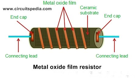
Metal film:
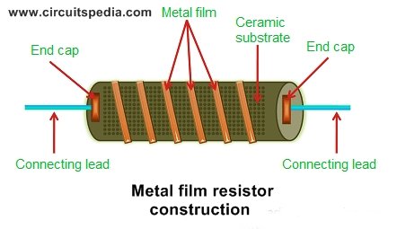
The metal film resistor construction is similar to the carbon film resistor except that the material used for constructing the film is different. This type of resistor uses a metal film. Metals such as nickel alloy may be used. In carbon film resistors, carbon is used to construct the film whereas, in metal film resistors, tin and antimony or nickel-chromium are used to construct the film. In the metal film resistors, the desired resistance value can be achieved by either trimming the thickness of the metal layer or by cutting the metal film in a helical manner along its length. This is generally done by using lasers. Once the desired resistance value is obtained, the cutting of metal is stopped. The metal film resistors are very similar to the metal oxide film resistor in terms of visual appearance and performance. The resistance of metal film resistors depends on the thickness of the metal film layer and the width of the helical metal film cut.
Wire wound:
A wire-wound resistor is a resistor where a wire with a high resistivity is wrapped around an insulating core to provide the resistance. The resistance value is dependent on the resistivity of the wire, the cross-section and the length. Since these parameters can be accurately controlled, high precision can be achieved. For high tolerance requirements, the resistance value is measured to determine exactly the cut to the length of the wire. To create a high resistance, the wire diameter needs to be very small and the length very long. Therefore wire wound resistors are mainly produced for lower resistance values. For low power ratings, a very thin wire is used. The handling of the wire is for this matter critical. Any damage may sever contact. After winding the wire is well protected. These resistors have quite different construction. Compared to other resistor types as the metal film, the wire diameter is relatively big and therefore more robust. 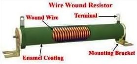
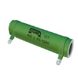
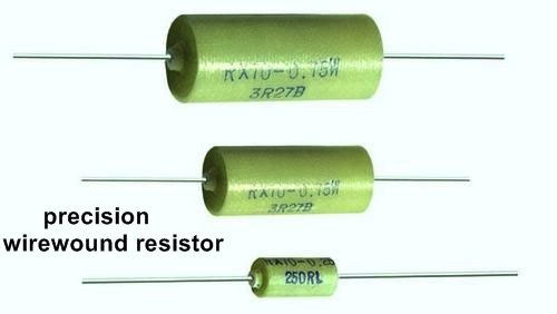
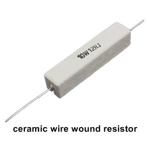
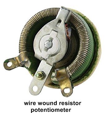
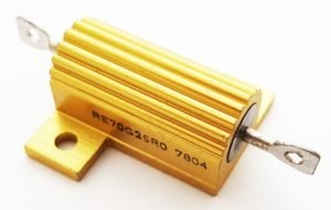
This resistor type is generally used in high power applications.. The more expensive varieties are wound on a ceramic former and they may be covered by a vitreous or silicone enamel. This resistor type is suited to high powers and exhibits a high level of reliability at high powers along with a comparatively low level of temperature coefficient, although this will depend on a number of factors including the former, wire used, etc.
Thin-film:
Thin film technology is used for most of the surface-mount types of resistors. As these are used in their billions these days, this makes this form of resistor technology one of the most widely used.
-
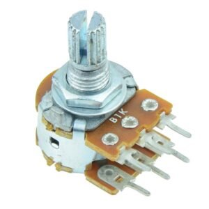
Variable resistors
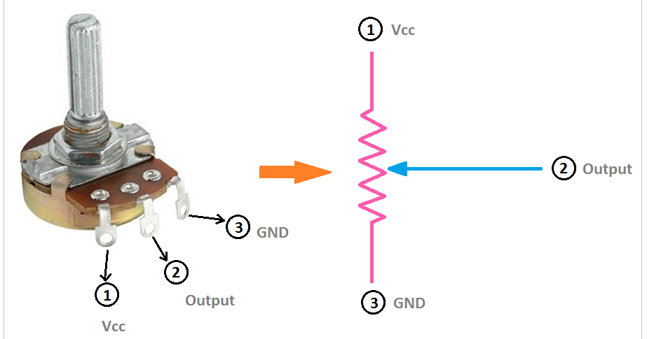
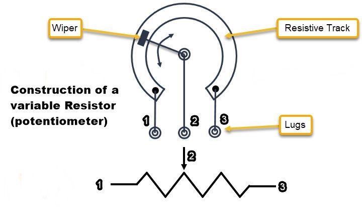
These resistors used in the adjustable value of Electric Resistance as required. This value can be changed manually. These consist of a fixed resistor element and a slider that taps onto the main resistor element. This gives three connections to the component, where two connected to the fixed element, and the third is the slider or movable. In this way, the component acts as a variable potential divider if all three connections are used. It is also to connect to the slider and only one end to provide a resistor with variable resistance.
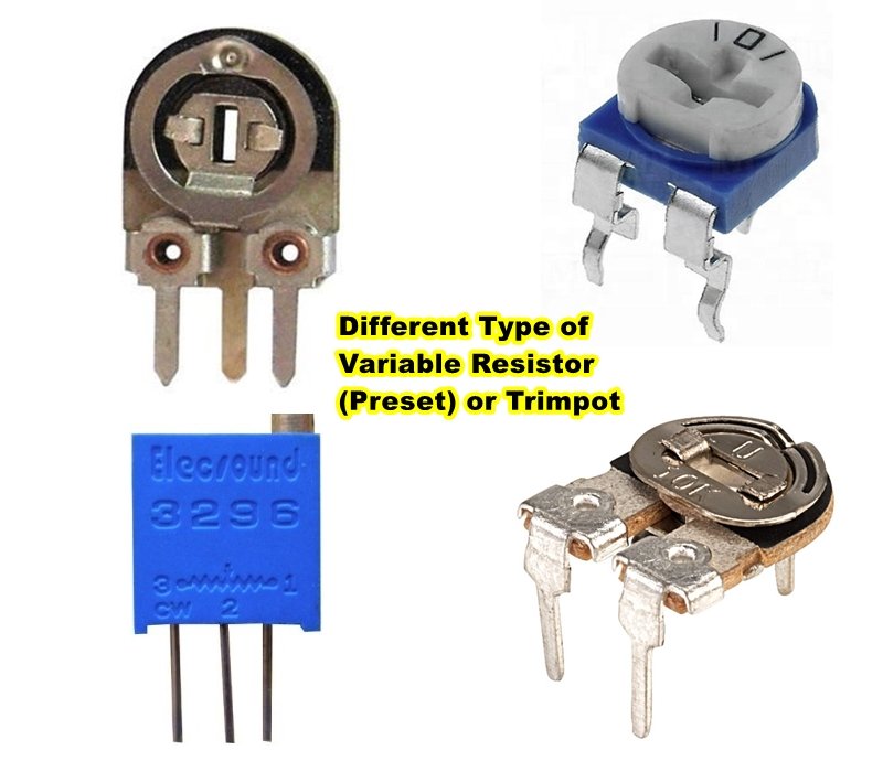
variable resistor also called Trimpot, Preset or Potentiometer (POT)
Termination and mounting
Through-hole (Leaded resistor)
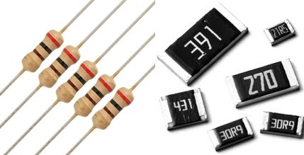
Through-hole resistors come with legs that easily entered through hole on the pcb board. Both terminals have legs of specific length which is used during connecting with other components using solder. This type of resistor are in axial size and take more space on circuit implementation. The size of an axial resistor is relative to its power rating. A common ½W resistor measures about 9.2mm across, while a smaller ¼W resistor is about 6.3mm long.
Must Read Method Of Ceramic Capacitor Code Reading
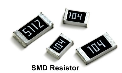
Surface mount (non-led) or SMD Resistors
Surface-mount resistors are mainly tiny size and rectangular shapes in black color. The terminal on its side with smaller, shiny, silver, with conductive edges. These resistors are intended to sit on top of PCBs, where they’re soldered onto mating landing pads. Because these resistors are so small, they’re usually set into place by a robot and sent through an oven where solder melts and holds them in place. SMD resistors come in standardized sizes; usually either 0805 (0.8mm long by 0.5mm wide), 0603, or 0402. They’re great for mass circuit-board-production, or in designs where space is a precious commodity. They take a steady, precise hand to manually solder.
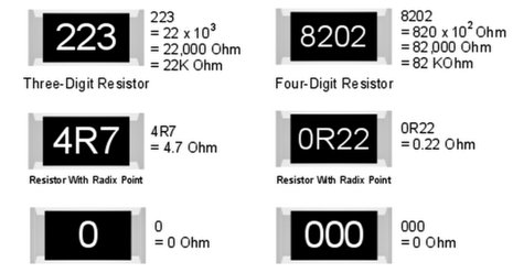
Surface Mount Resistors are printed with either a 3 or 4-digit numerical code which is similar to that used on the more common axial type resistors to denote their resistive value. Standard SMD resistors are marked with a three-digit code, in which the first two digits represent the first two numbers of the resistance value with the third digit being the multiplier, either x1, x10, x100 etc. For example
103 = 10 × 1,000 ohms = 10 kiloΩ
392 = 39 × 100 ohms = 3.9 kiloΩ
563 = 56 × 1,000 ohms = 56 kiloΩ
105 = 10 × 100,000 ohms = 1 MegaΩ
Surface-mount resistors that have a value of less than 100Ω’s are usually written as: “390”, “470”, “560” with the final zero representing a 10 xo multiplier, which is equivalent to 1. For example:
390 = 39 × 1Ω = 39Ω or 39RΩ
470 = 47 × 1Ω = 47Ω or 47RΩ
Resistor Color Code
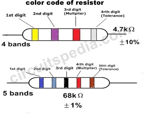
How to read color code of resistor
Must Read What is 555 Timer
Method of finding the value of the through-hole resistor
• Digit digit multiplier tolerance (for 4 band resistor )
• Digit digit digit multiplier tolerance (for 5 band resistor)
Yellow Violet Red = 4 7 2 = 4 7 x 102 = 4700Ω or 4.7or 4k7.
Color code of Resistor
Yellow Violet Red = 4 7 2 = 4 7 x 102 = 4700Ω or 4.7or 4k7.
Green Grey Black Red Brown=5 8 0 2 = 680×102 =58k Ohms
Tolerance: ±1%
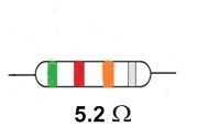
If A resistor colored Green–Red–Gold–Silver then its value is 5.2 Ω and tolerance of +/- 10%.
A resistor-colored Brown–Green–Grey–Silver-Red would be 1.58 Ω with a tolerance of +/- 2%.
Color Code Table of Resistor
Must Read Method Of Ceramic Capacitor Code Reading
Series connection
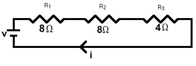
A series circuit is a circuit in which resistors are arranged in a chain, so the current has only one path to take. The current is the same through each resistor. The total resistance of the circuit is found by simply adding up the resistance values of the individual resistors:
equivalent resistance of resistors in series : R = R1 + R2 + R3 + ….
series circuit is shown in the diagram above. The current flows through each resistor in turn. If the values of the three resistors are:
R1=8 Ω , R2= 8 Ω , R3=4Ω then total resistance = 8+8+4= 20 Ω
With a 10 V battery, by V = I R the total current in the circuit is:
I = V / R = 10 / 20 = 0.5 A. The current through each resistor would be 0.5 A
Parallel connection
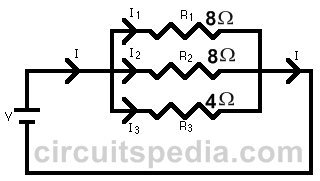
A parallel circuit is a circuit in which the resistors are arranged with their heads connected together, and their tails connected together. The current in a parallel circuit breaks up, with some flowing along each parallel branch and re-combining when the branches meet again. The voltage across each resistor in parallel is the same.
The total resistance of a set of resistors in parallel is found by adding up the reciprocals of the resistance values, and then taking the reciprocal of the total:
equivalent resistance of resistors in parallel: 1 /R = 1 / R1 + 1 / R2 + 1 / R3 +….
A parallel circuit is shown in the diagram above. In this case the current supplied by the battery splits up, and the amount going through each resistor depends on the resistance. If the values of the three resistors are:
R1=8 Ω , R2= 8 Ω , R3=4Ω then total resistance =1/R=1/8+1/8+1/4
1/R=1/2, then R=2 Ω
With a 10 V battery, by V = I R the total current in the circuit is: I = V / R = 10 / 2 = 5 A.
• Resistor Color Code Calculator
Select Number of Bands
Resistor Parameters
1st Band of Color-
Select a Color

-
-
Black0
-
Brown1
-
Red2
-
Orange3
-
Yellow4
-
Green5
-
Blue6
-
Violet7
-
Grey8
-
White9
-
-
Select a Color

-
-
Black0
-
Brown1
-
Red2
-
Orange3
-
Yellow4
-
Green5
-
Blue6
-
Violet7
-
Grey8
-
White9
-
-
Select a Color

-
-
Black×1 Ω
-
Brown×10 Ω
-
Red×100 Ω
-
Orange×1 kΩ
-
Yellow×10 kΩ
-
Green×100 kΩ
-
Blue×1 MΩ
-
Violet×10 MΩ
-
Grey×100 MΩ
-
White×1 GΩ
-
Gold×0.1 Ω
-
Silver×0.01 Ω
-
-
Select a Color

-
-
Brown± 1%
-
Red± 2%
-
Green± 0.5%
-
Blue± 0.25%
-
Violet± 0.1%
-
Grey± 0.05%
-
Gold± 5%
-
Silver± 10%
-
Output

Resistor value:
Must Read

