LED Flasher/Blinking Circuit diagram Using 555 timer
This is a Popular and Simple LED Flasher circuit using one 555 timer ic and some other components.
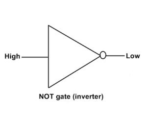
This circuit works on the principle of Astable Mode operation of 555 timer. Which produces a continuous Pulse wave at the output on pin 3. When the pulse signal is High then one connection of LED gets positive supply through pin 3. and then again when Low output pulse produces then the negative supply goes to second connection of LED.
When negative supply is given through pin 3 then the LED gets positive supply through directly VCC. And When positive supply given by pin no 3 then negative supply gets from the directly negative supply of battery. Therefore both LED connections to get continuous a positive and negative supply and Flashing according to the output of pin 3.
The speed can be changed by moving the preset R1 or changing the capacitor value of c1.
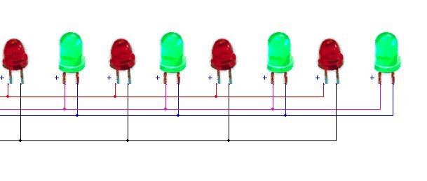
You can arrange the LEDs as your own choices with different patterns. You can operate 10-12 LEDs easily without any issue with this circuit.
components
555 timer IC – 1
470Ω resistor – 2
10KΩ resistor – 1
Preset 100K – 1
Capacitor 10uf 25v -1 , 0.1uf (104) -1
LEDs Minimum 2


como trabajan los ci. 4016b 4017b y 4060 para q prendan los lde en dos tiempos y el parpadeo sea mas de 5 6 vese luego anbos parpadean
como trabajan los ci. 4016b 4017b y 4060 para q prendan los lde en dos tiempos y el parpadeo sea mas de 5 6 vese luego anbos parpadean
If you connect and construct Properly with constant Power Supply, Then this work very stale