Automatic Water level pump controller for submersible motor
Water pump controller circuit will automatically stop the motor pump when the tank is full.
Description.
At many times when the water tank is empty, we start the motor for storing the water in the tank and get busy in other work. Then we forget to switch off the water pump motor after the tank is full. In this case, water is overflowing from the tank and an unusually amount of water is wasted. This Automatic Water Pump Controller circuit is best suited for the submersible motor pump.
We need to save water from wastage by overflowing. Electricity is also more extra consumed by the motor when the motor is running after the tank is full, so it is difficult to stop the motor manually at the exact time when the tank is full if your water tank is so far from the living room.
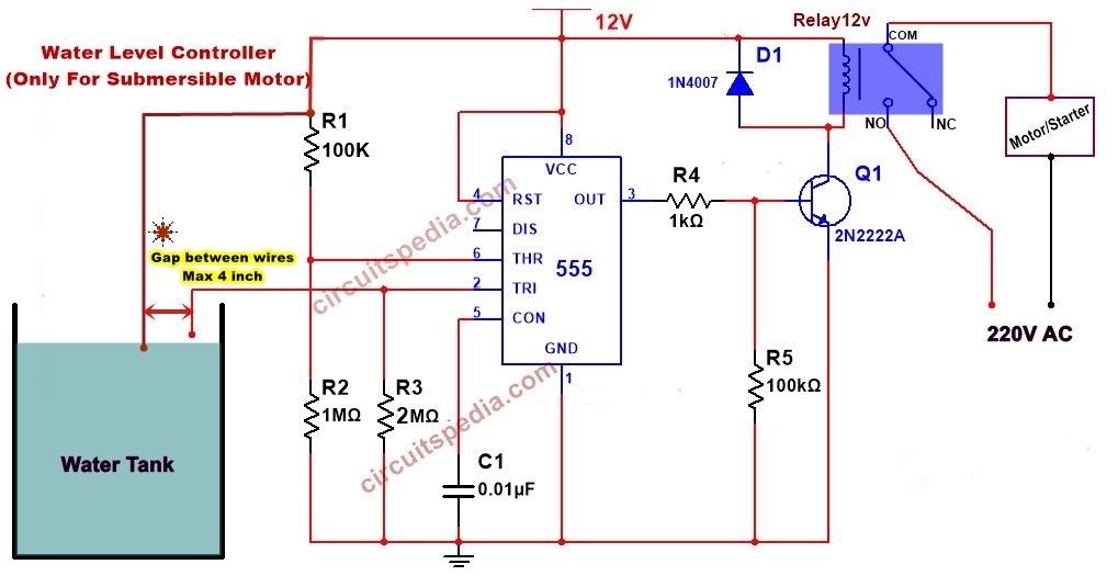
A simple but very reliable and effective Automatic water pump controller circuit diagram is shown here, which is able to stop the motor pump automatically when the tank is full. The circuit uses 1 transistor, 1 NE555 timer IC, a relay, and a few passive components. The circuit is completely automatic, which stops the pump motor when the water level in the overhead tank goes to a preset (at the top) level. Switches OFF the pump when the water level in the overhead tank goes to touch with top-level wire fitted in-tank i.e the full level.
Also, read Automatic Water Pump Controller Without IC
Connect the circuit diagram as shown in Fig and use the dc power supply by battery or adaptor to operate this circuit. This circuit works well with 12v DC power. Two wires are positioned as a sensor, one at the bottom level of the tank and one is the upper top level where required to before overflow. Use 12v relay of min 25 Ampere load capacity. The circuit is easy to construct and economical, highly reliable.
Working
When the water level reaches the upper wire contacts, the voltage at pin 6 of the IC goes high, and then the internal S-R flip-flop of ic goes in sets, and its output goes low. This low output at pin 3 switches off the transistor and de-energizes the relay and disconnects the motor power supply
When the tank’s water level goes below the low level, the voltage of pin 2 of the IC becomes low. The internal flip-flop of IC resets, and its output goes high. This high output at pin 3 switches on the transistor in one state and then the relay energizes the relay.
parts
Resistor
100k-1
1M-1
2M-1
100k-1
1K-1
ic- 555-1
Relay–
12v 10A-1
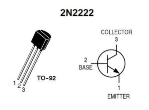
Transistor– BC547(for small pcb mount relay), 2N2222 for high current Load relay
Diode 1N4007
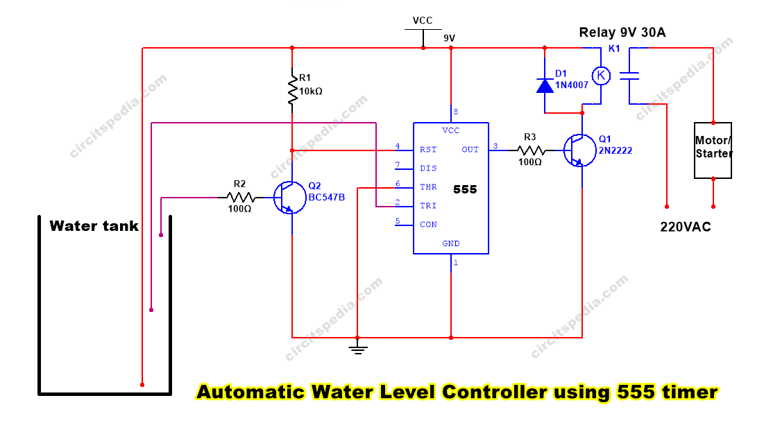
Circuit diagram 2
The motor will start only when the Water level goes below from the middle wire means the motor will not start again until the level goes below half. This circuit works in the bistable mode of 555 timer.
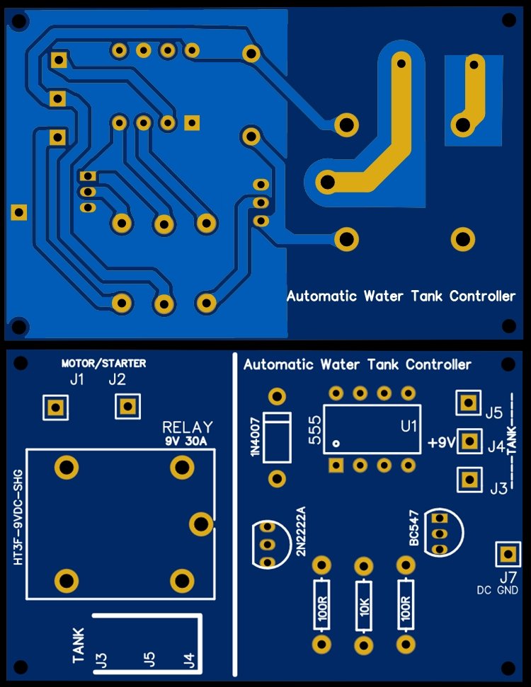
PCB Layout of Circuit 2
Must read



how many output voltage in pin no 3 of ic
Nice Post.. Its Helpfull.. Thank You.. you are Awesome.
This is a fantastic project! The detailed explanation of using the 555 timer for automatic water pump control is very helpful. I’m excited to try this out for my own submersible setup. Thanks for sharing the circuit diagrams and the troubleshooting tips!
This is a fantastic project! I’ve been looking for ways to automate my water pump system, and your detailed explanation of the 555 timer circuit makes it seem so doable. I appreciate how you broke down each component and its function. Can’t wait to try this out in my own setup!
This is a fantastic project idea! The use of the 555 timer for controlling a submersible pump is both clever and practical. I appreciate the detailed explanation and the clear diagrams. Can’t wait to give this a try!