AC dimmer Arduino
What is dimmer
A dimmer is a circuit that controls the voltage level by changing its waveform and gives output minimum or less than the input, and makes the brightness of light dim or changes the speed of the fan as the required level.
AC dimmers are mainly of two types: one is manual, and the second is automatic. In manually dimmer circuit dimming can be created using an adjusting of moving knob of a Potentiometer or any variable resistor as a required output voltage level. In automatic Dimmer, the dimming effect is created using a predefined level and time duration.
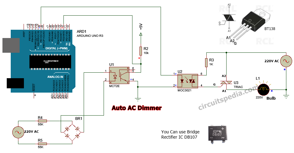
An automatic dimmer can be used in any AC decorative lights for getting a special effect and for the automation of devices. This one channel ac dimmer is made using the Arduino UNO board using a specified coding.
AC dimmer circuit is made by using Triac and optocoupler. A zero-cross detector circuit is required for ac dimming purposes. This provides a stable signal at every zero level of the waveform and sends a signal to Arduino to know about each zero level of a sine waveform.
Triac is firing for microseconds on each pulse continuously. Pin 2 of the digital pin in Arduino is an interrupt pin that is used here for providing a delay in firing the triac. Then, the output will create a dimming signal by cutting the edge of a part of the waveform of sine.
Note – This circuit uses 220v ac, so this is very dangerous. So very careful when testing. If you are not sure about working with ac supply then don’t test it because it can cause death.
Schematic diagram
dimmer Arduino
Components Required
Bridge rectifier ic DB107 – 1
Optocoupler IC MCT2E or 4N35 – 1
Optotriac IC MOC3021 – 1
Triac BT136 or BT138 – 1
Arduino UNO Board – 1
Resistors
56K- 2
10K-1
1K -1
arduino dimmer code
Code /*AC Light Control Changed zero-crossing detection to look for RISING edge rather than falling. (originally it was only chopping the negative half of the AC wave form). Also changed the dim_check() to turn on the Triac, leaving it on until the zero_cross_detect() turn's it off. #include <TimerOne.h> // Avaiable from http://www.arduino.cc/playground/Code/Timer1 volatile int i=0; // Variable to use as a counter volatile as it is in an interrupt volatile boolean zero_cross=0; // Boolean to store a "switch" to tell us if we have crossed zero int AC_pin = 9; // Output to Opto Triac int dim = 0; // Dimming level (0-128) 0 = on, 128 = 0ff int inc=1; // counting up or down, 1=up, -1=down int freqStep = 75; // This is the delay-per-brightness step in microseconds. // For 60 Hz it should be 65 // It is calculated based on the frequency of your voltage supply (50Hz or 60Hz) // and the number of brightness steps you want. // // Realize that there are 2 zerocrossing per cycle. This means // zero crossing happens at 120Hz for a 60Hz supply or 100Hz for a 50Hz supply. // To calculate freqStep divide the length of one full half-wave of the power // cycle (in microseconds) by the number of brightness steps. // // (120 Hz=8333uS) / 128 brightness steps = 65 uS / brightness step // (100Hz=10000uS) / 128 steps = 75uS/step void setup() { // Begin setup pinMode(AC_pin, OUTPUT); // Set the Triac pin as output attachInterrupt(0, zero_cross_detect, RISING); // Attach an Interupt to Pin 2 (interupt 0) for Zero Cross Detection Timer1.initialize(freqStep); // Initialize TimerOne library for the freq we need Timer1.attachInterrupt(dim_check, freqStep); // Use the TimerOne Library to attach an interrupt // to the function we use to check to see if it is // the right time to fire the triac. This function // will now run every freqStep in microseconds. } void zero_cross_detect() { zero_cross = true; // set the boolean to true to tell our dimming function that a zero cross has occured i=0; digitalWrite(AC_pin, LOW); // turn off TRIAC (and AC) } // Turn on the TRIAC at the appropriate time void dim_check() { if(zero_cross == true) { if(i>=dim) { digitalWrite(AC_pin, HIGH); // turn on light i=0; // reset time step counter zero_cross = false; //reset zero cross detection } else { i++; // increment time step counter } } } void loop() { dim+=inc; if((dim>=128) || (dim<=0)) inc*=-1; delay(60); } Also read Distance measurement using arduino


