Digital thermometer design and development using Arduino UNO and LM35 temperature sensor
Arduino LM35 Temperature Sensor with LCD display
Thermometers enable us to read the temperature in any room, space or region. Thermometers are widely used in industries for temperature monitoring during the manufacturing process. Similarly, thermometers are of vital importance at hospitals, especially in incubation units. The need of analog thermometers is decreasing with the passage of time as analog thermometers cannot be used for remote monitoring of temperature, they are slow and obsolete. However, digital thermometers are developed with microcontrollers nowadays and offer various features that make them more practical and useful. For example, digital thermometers can be used in remote areas where the physical presence of an operator is impractical such as in hot furnace at an industry. The thermometer reads temperature and wirelessly transmits signals to the mobile or HMI system in the monitoring room. Furthermore, the temperature range can be set to Celsius or Fahrenheit according to requirement and can be displayed on a screen or in the form of LED display.
In this project, a complete design and development procedure of a digital thermometer has been discussed. The algorithm used in this design is simple and easy to understand. The components used are limited and readily available in the market. Although the overall development of this project is low cost and easy still the results are extraordinary. Let’s see how this design works.
Theory
Arduino and LM35 based digital thermometers can be developed at home with very few components and instruments needed. Arduino UNO used in this design is a microcontroller which is responsible for data handling and processing for temperature calculation and display. Arduino UNO has digital I/O and Analog pins. In this case, we are using both.
LM35
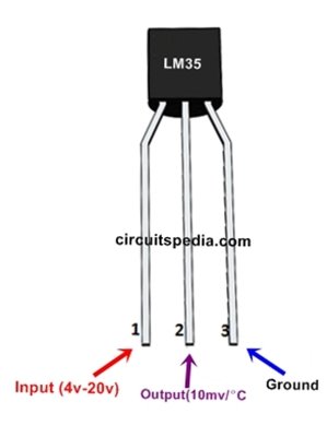
The next component is LM35 which is a temperature sensor and looks more like a simple BJT. LM35 is cheap as compared to most of the temperature sensors and yet offers a high level of accuracy even at extreme temperatures. LM35 can be used in both analog circuits and embedded systems since it offers analog voltages at the output.
Calculation of temperature is not enough, to display our results, HDD44780 driver based 16×2 LCD has been used. 16×2 stands for 16 rows and 2 columns incorporated in this design. This model is widely used for simple display as it is low cost and works efficiently. The LCD is compatible with Arduino as the protocols involved are satisfied at both ends. The LCD is available in 16×4 configuration too in case if more rows are needed.
Let’s take a look at the necessary components.
Components required
The components required for this design are:
Arduino UNO MCU
LM35 temperature sensor
16×2 LCD (HDD44780 driver based)
6v battery or 5v USB power source (Mobile adapter/laptop)
Jumper wires
Breadboard
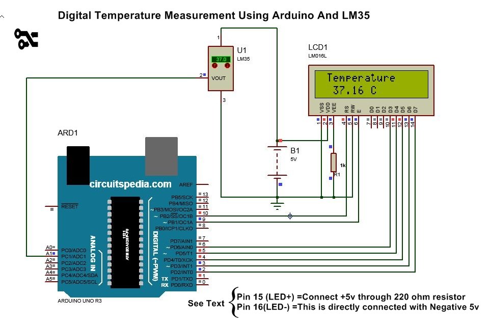
schematic diagram
Pin 15 and Pin 16 Of LCD is for Backlight. If these not connected then only the backlight will remain off. Connect pin 15 of LCD with +ve 5v. This is the positive terminal of Backlight LED. Pin 16 is the negative terminal of the backlight LED, so pin 16 is Grounded.
Arduino lm35 sensor simulation
Simulation
The circuit diagram described in the figure is simple and can be easily modified if needed. Whenever designing a circuit, it is recommended first to simulate and check if the results are according to requirements. Since simulation can be easily modified with a few clicks but hardware is difficult to modify as the soldering, unsoldering, troubleshooting can be hectic and time-consuming.
This simulation has been created on Proteus 8 and the libraries used are easily available on the internet. First of all, add all necessary components and connect them as illustrated in the circuit diagram.
The pin configuration of all components must be carefully considered as one wrong connection can result in improper or no functioning of design.
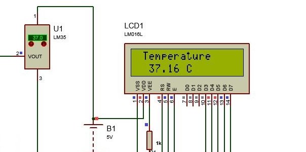
LM35 offers analog voltages with respect to the temperature it is kept in. Since the temperature cannot be changed in simulation, the simulated model can be controlled using the temperature buttons. As the temperature for a simulation model of LM35 is variated, the instructions for rising temperature are forwarded to the sensor. LM35 offers rise of 10mv/degree Celsius.
As these output voltages of LM35 are analog and analog values cannot be directly processed by the MCU, these values are first passed to Analog to Digital Converter. The digitally converted value is further processed as per the algorithm. These digital inputs are used for the calculation of temperature in degree Celsius and Fahrenheit.
The temperature is further displayed on the LCD connected with Arduino. The LCD has data pins, read/write enable configurations for further features.
It is essential to connect each connection as demonstrated in simulation. The battery source voltage must be maintained 5v. Although in simulation, even if voltages exceed 5v, they cause no harm to the components but practically, the rated voltages of components must be considered. Exceeding 5v can permanently damage components.
After making all necessary connections, ensure each connection and value of the component is according to the design. Add the hex file of code in Arduino UNO’s simulation model. The hex file serves as the machine language instruction for the MCU.
Run the simulation and observe functioning by varying temperature on the sensor. If the temperature on the LCD varies just according to the temperature changes made on the sensor, the simulation is working correctly.
If the temperature displayed on the LCD is not changing with respect to the sensor’s temperature, check the connection of the sensor with Arduino and ensure the MCU coding is according to the code supplied. If the there is no display on the LCD, the connections between LCD and Arduino might be wrong or alternatively, the library of LCD or commands must be inaccurate in code.
Also Read
-
Ultrasonic distance measurement Arduino
-
What is Fusible resistor
-
Clap ON OFF Switch Using 555 and 74LS74
-
Bird Sound Generator Circuit Using Arduino
-
Multi Pattern LED Chaser using arduino
Arduino Coding
The code for Arduino UNO has been simulated on Arduino IDE. Fortunately, Arduino IDE offers impressive functions such as runtime results of code on Serial Monitor and loads of builtin libraries.
The code starts with a declaration of LCD library and pin configuration for Arduino UNO. All the variables and pin configurations are defined in the beginning.
In the setup function, LCD is initialized with commands and the baud rate is set for proper communication.
The main part of the code is present in the loop function which is supposed to run over and over again unless the power supply for MCU is cut off.
The Analog to Digital conversion is performed and the temperature is in Celsius is calculated. This temperature is displayed on the serial monitor which can be observed only if the hardware is connected. The measured temperature is then displayed on the LCD with specific commands.
// Digital Thermometer

#include <LiquidCrystal.h>
LiquidCrystal LCD(10, 9, 5, 4, 3, 2);
float tempC;
int reading;
int tempPin = 1;

void setup()
{
LCD.begin(16,2);
LCD.setCursor(0,1);
LCD.print("    ");
LCD.setCursor(0,0);
LCD.print("    ");

analogReference(INTERNAL);
Serial.begin(9600);
}

void loop()
{
 reading = analogRead(tempPin);
 tempC =  reading / 9.31;
 Serial.println(tempC);

 LCD.setCursor(0,0);
 LCD.print(" Temperature ");

 LCD.setCursor(0,1);
 LCD.print("  ");
 LCD.print(tempC);
 LCD.print(" C  ");
 delay(200);
 LCD.setCursor(0,1);
 LCD.print("   ");
}




Nice. Can you post a simulation code for thermometer with arduino, dht11 and add some programmable alarm in it?
Is it possible to simulate the same design and code with Arduino Mega?
Connection and program should changed as different board type. Then simulation possible.
Please post an article on Arduino and LM35 based automated incubation machine
Thanks for the detailed project