Contents
Zener diode
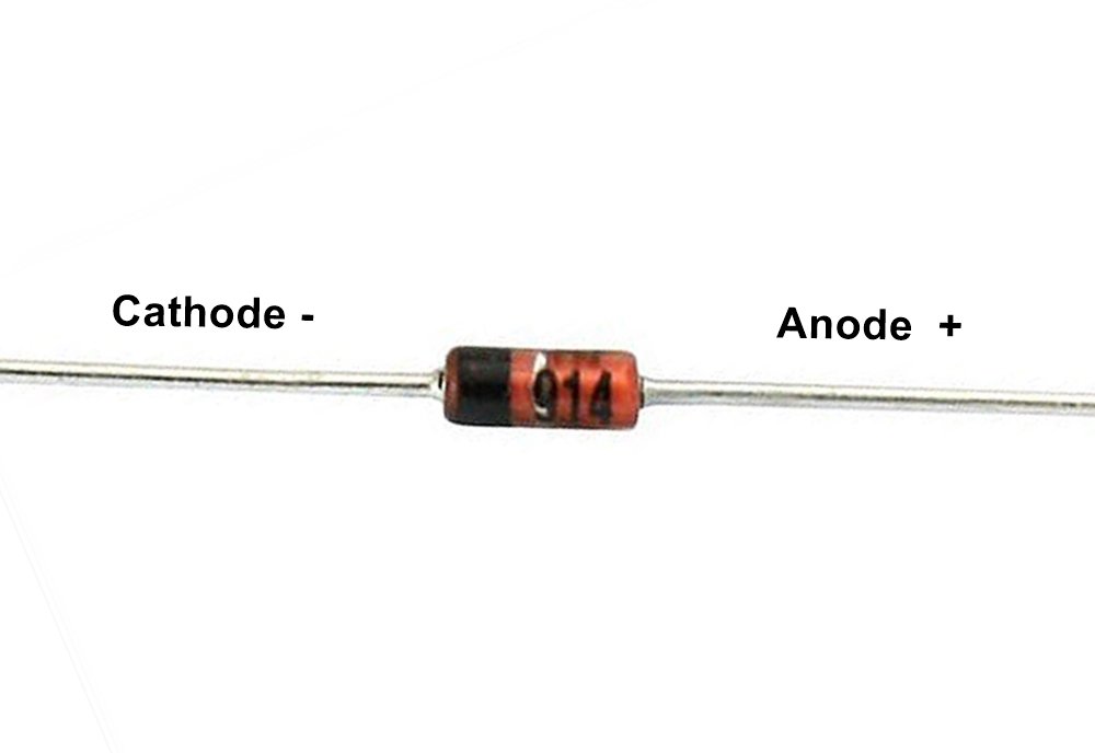
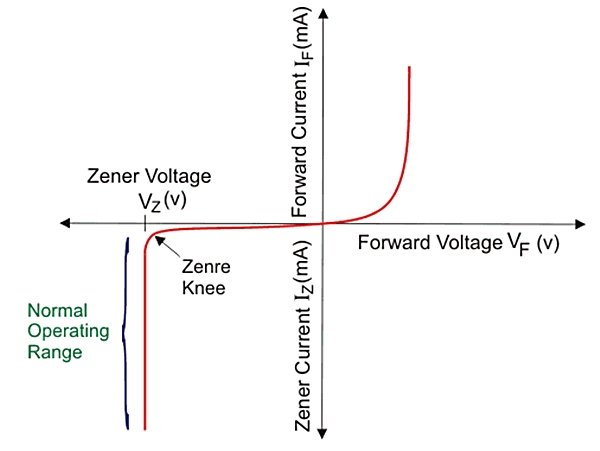
Zener diode is a type of diode that flows of current also in reverse bias and in applications, it is always connected in reverse bias and Zener diode limits the voltage, this diode is used for regulating the voltage in any circuit. It always works in Zener breakdown voltage. Zener breakdown voltage is the voltage level at this Zener diode that starts the current conduction in reverse bias. When reverse voltage increases then current conduction starts at a level, this level of voltage is called breakdown voltage and the current flowing through the diode is called Zener current. This process is called avalanche breakdown.
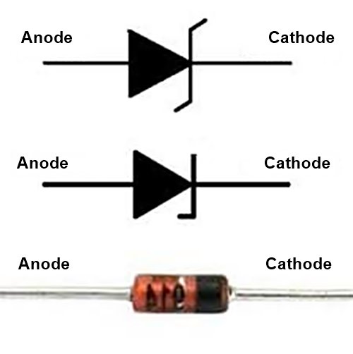
First, we take a look at the normal diode. A normal diode works only in forward bias, which means the voltage on the cathode is less than the anode. The voltage on the anode is high with respect of the cathode then it is called forward bias, in this condition, a normal diode starts conduction. If the voltage on the anode is 2v and voltage on the cathode is 0v or the voltage on the anode is 5v and 2v on the cathode then conduction starts and the diode will work, but if the voltage on the anode is 0v and the voltage is on the cathode is 2v then the normal diode will not work and this is called reverse connection.
In reverse bias after a limitation of current flow barrier break and a reverse current flow
A normal diode only works in forward bias. If we give voltage more than breakdown voltage in reverse bias in normal diode then it will damage permanently. This drawback of the normal diode was removed in the Zener diode. A Zener diode works as a normal diode If it is connected in forward bias. But Zener diode also conducts current in reverse bias connection with the specified condition.
Zener diode as a voltage regulator
We try to understand how the Zener diode works and regulates the voltage.
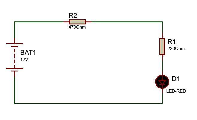
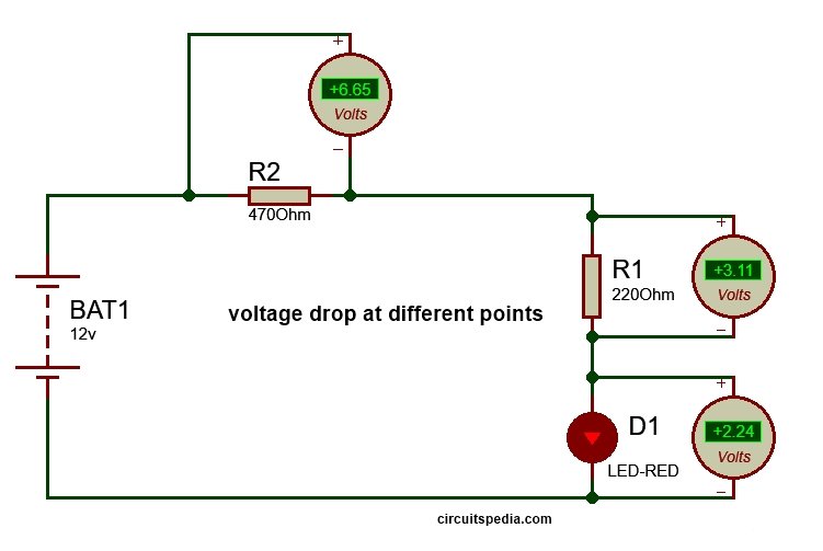
V1 (BAT1) is a DC source, a load is connected and denoted as RL, and a Zener diode is connected across the RL through a resistor. In this circuit anode of the Zener diode is connected with the negative terminal of the battery and the cathode of Zener is connected to a positive point of the battery. So this connection is in reverse bias. 12v DC source or battery applied and R1 is 220 ohm, R2 is 470 ohm and an LED is connected with R1 as Load.
Also read Logic gates concept
Now we check the voltage at all resistors and load, voltage is divided at all resistors and load according to resistances at each point as divider formula. I connect three DC voltmeters at each resistor and load to measure the Voltage Drop at each part. As you see in the circuit diagram given Voltage drop across R1 = 3.114v, across R2= 6.65v and voltage drop at load (LED)=2.24v. so, 3.11v+6.65v+2.24v+6.65v=12v
In this circuit arrangement, the total voltage across the load is 2.24v (Here load is LED). If i want to the voltage at load fix 3v But input source voltage remains 12v, then what should i do?
Zener diode circuit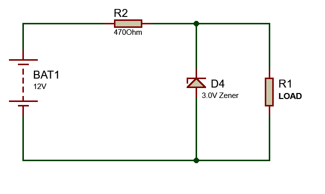
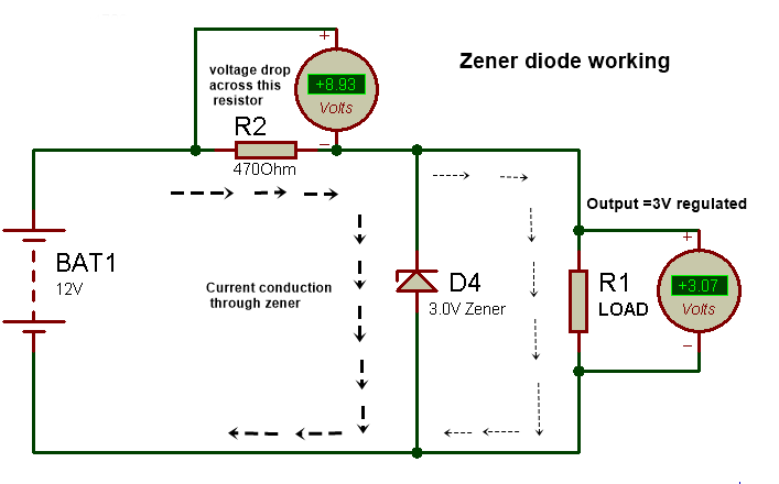
For 3v output, we should connect a 3v Zener diode to parallel with the output load. One thing is noted here that a resistor must connect before the Zener as a series with positive voltage. But here is a Question about this resistor, Why use this resistor?
Why do I connect a resistor with Zener diode?
When we connect the Zener diode at the output in reverse bias, then-current through the diode pass according to the source voltage. Here source voltage is 12v which is fix. If the source voltage increase then the current conduction through the Zener diode also increases and the extra voltage drop at the resistor R2. If the source voltage varies then the current conduction through the Zener diode and resistor also varies and all varied extra voltage will drop at resistor R2 and we found a fixed regulated voltage at the output. So all extra voltage will drop at the resistor that is connected in series with Zener. It means according to applied input voltage increases, the Zener diode allows to pass more current through itself by the series resistor, therefore, the current conduction through resistor and Zener diode increase as per input voltage, and the point of Zener diode we get regulated fix voltage as its rating.
If you need 3v output then use 3v or 3.1v Zener diode and according to if you need 5v then use 5.1v and 9v Zener for 9v output 12v Zener for 12v output…..But the applied input voltage Must be higher than the required output voltage because the Zener diode always works in the breakdown region so for breakdown the applied voltage should be higher than the breakdown voltage.
There are limitations to the current conduction capacity of each Zener. Zener diode is available in the market at the rating of a different watt with different voltages.
The value of the series resistor can be determined by using the following given formula
R=(Vin -Vz)/Iz
Where R= Series resistor
Vin= Applied input voltage
Vz= Zener voltage (this is equal to Output voltage V0)
Iz= Zener current
Important FAQ(Frequently asked questions)
Q: What is a Zener diode?
A: A Zener diode is a type of diode that operates in the reverse breakdown region, maintaining a nearly constant voltage drop across its terminals when a specific voltage, known as the Zener voltage, is reached.
Q: How does a Zener diode work?
A: A Zener diode works by utilizing the Zener breakdown mechanism. When the reverse bias voltage applied to the diode exceeds the Zener voltage, a significant amount of current starts to flow through the diode, resulting in a stable voltage drop across its terminals.
Q: What is the Zener breakdown voltage?
A: The Zener breakdown voltage is the voltage at which a Zener diode enters the breakdown region and starts to conduct significant current in the reverse bias direction. It is a crucial parameter for Zener diodes and determines their voltage regulation capabilities.
Q: What are the applications of Zener diodes?
A: Zener diodes have various applications, including:
- Voltage regulation: They are commonly used as voltage regulators to maintain a constant voltage across a load.
- Voltage reference: Zener diodes can provide a stable voltage reference for other components in a circuit.
- Overvoltage protection: They can be employed to protect sensitive components from voltage spikes by clamping the voltage to a safe level.
- Waveform clipping: Zener diodes can be used to clip or limit the amplitude of input signals, useful in waveform shaping applications.
- Noise generation: They can generate random noise signals for various applications, such as testing and cryptography.
Q: How is the Zener voltage specified for a Zener diode?
A: The Zener voltage, or breakdown voltage, is specified in datasheets or product specifications as the nominal voltage at which the Zener diode enters the breakdown region. It is typically specified at a specific test current, such as the Zener test current (Iz).
Q: What is the power rating of a Zener diode?
A: The power rating of a Zener diode refers to its ability to dissipate power without being damaged by excessive heat. It is important to select a Zener diode with a power rating suitable for the anticipated power dissipation in the application.
Q: How does temperature affect the characteristics of Zener diodes?
A: Temperature can influence the Zener voltage of a diode. Typically, the Zener voltage decreases with an increase in temperature. Therefore, temperature variations should be considered when designing circuits using Zener diodes to ensure stable voltage regulation.
Q: How does a Zener diode differ from a regular diode?
A: A regular diode is designed to conduct current in the forward bias direction and block current in the reverse bias direction. In contrast, a Zener diode is specifically designed to have a sharp breakdown voltage in the reverse bias direction and operate in the breakdown region.
Q: Can Zener diodes be used in the forward bias direction?
A: Yes, Zener diodes can be used in the forward bias direction like regular diodes. However, their forward voltage drop is higher compared to standard diodes, so they are not typically used in this mode.
Q: Are Zener diodes available in different voltage ratings?
A: Yes, Zener diodes are available in a wide range of voltage ratings to suit various application requirements. The voltage ratings typically range from a few volts to several hundred volts.
Q: What are the factors to consider when selecting a Zener diode for an application?
A: When selecting a Zener diode, consider factors such as the desired Zener voltage, power rating, maximum current, breakdown voltage tolerance, temperature coefficient, and package type to meet the requirements of the specific application.
Q: Can Zener diodes handle high currents?
A: Zener diodes are generally designed to handle low to moderate currents. For applications requiring high currents, it is common to use external circuitry, such as a series resistor, to limit the current flowing through the diode.
Q: Are Zener diodes available in different voltage ratings?
A: Yes, Zener diodes are available in a wide range of voltage ratings to suit various application requirements. The voltage ratings typically range from a few volts to several hundred volts.
Q: Can Zener diodes be used in AC circuits?
A: Yes, Zener diodes can be used in AC circuits. However, it is important to consider the voltage polarity and ensure the diode is properly connected in the circuit to ensure it operates in the desired direction.
Also read
