Arduino remote control AC Dimmer
The brightness can be controlled using the IR remote of TV, DVD, etc. Dimming Control system using MOC3021, BT136 Triac and a zero-crossing detector circuit based on the MCT2E optocoupler. Optocoupler provides complete isolation between the AC side and the DC controller side. So if any fault or short circuit happens on the AC side will have no effect on the controller side.
In this tutorial, we will design a circuit using TRIAC and optocoupler to make a 220V AC Light Dimmer or AC Fan Speed Controller using Arduino UNO. most of the home appliances are supplied with the AC mains power. Sometimes we need to control the brightness of bulb or Speed of Fan/ AC Motor etc or any other dimming control for an instant. Controlling an AC load is not as easy as controlling a DC load. The AC mains with a sinusoidal wave have the frequency of 50Hz to 60 HZ.
The most popular and proper way for Dimming of 230v AC is through phase control with a Triac. To build an AC dimmer, the zero-crossing detector circuit used and zero-crossing points (the points where the wave changes its polarity) are important. A zero-crossing detector is used to generate a sync pulse related to the AC voltage phase angle often used in power control circuits. Zero crossing detector basically detect zero voltage points and inform the controller or controller circuit. It helps to minimize high rate change of current with respect to time (dI/dt) as a result less heating and start-up current in the load which improves the lifetime of load such as motors. A Zero Crossing Detector can be designed in many ways like using transistor, using op-amp or using optocoupler IC
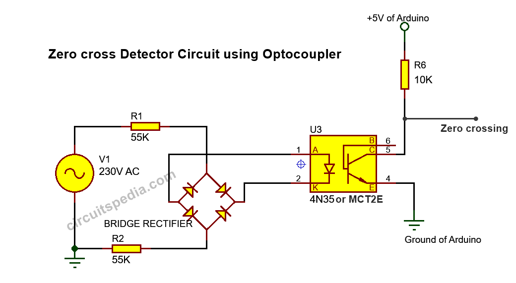
- bridge rectifier converts ac into dc
- Output of bridge rectifier is fed to opto-coupler
- Led inside the optocoupler requires minimum of 1V to turn on
- when ac wave goes near to the zero crossing line,ie below 1V led will turn off
- as a result output transistor will turn of and pulled up to 5v
The zero-crossing technique is one of the methods enabling to evaluate the delay time of propagating waves.
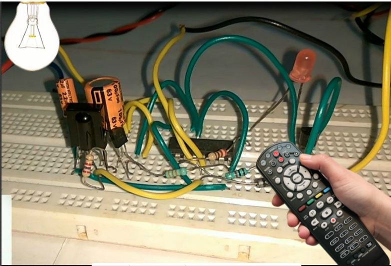
In this project I’m going to show how to a remote used to control the circuit for the Dimmer, so that the lamp brightness is controlled from IR remote control instead of the potentiometer.
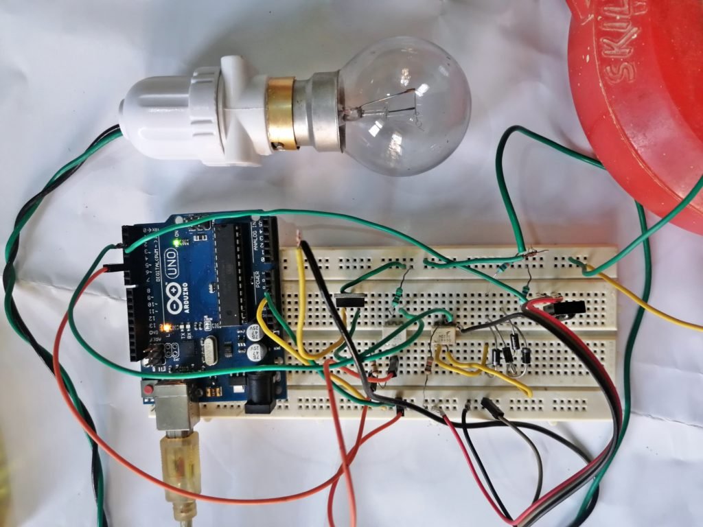
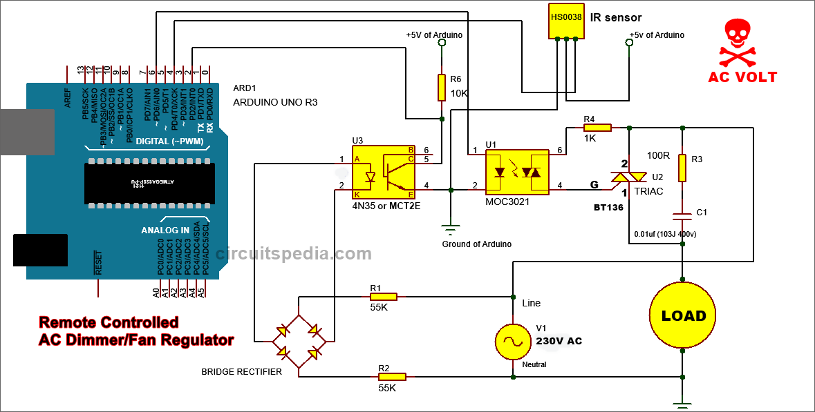
Connect the circuit as per the given schematic diagram. You can use DB107 or other bridge rectifier ic at the place of 4 separate 1N 4007 diodes. Here I use 2 55k resistor to limit the current from AC input to rectifier, an Optocoupler ic connected, here 4N35 is connected but you can use MCT2E or PC817 etc. In optocoupler ic there is an LED and NPN transistor. connect negative supply from bridge rectifier to pin 2, this is the negative pin of the LED of the optocoupler. the positive terminal of LED at pin 1 in this optocoupler. The emitter of the transistor is connected with the ground pin of Arduino and collector pin which is at pin 5 of optocoupler ic is directly connected with digital input pin of Arduino and one 10K resistor is with pin 5 is connected to +5v of Arduino, here this resistor is working as a pull-up resistor.
Schematic diagram
Triac–
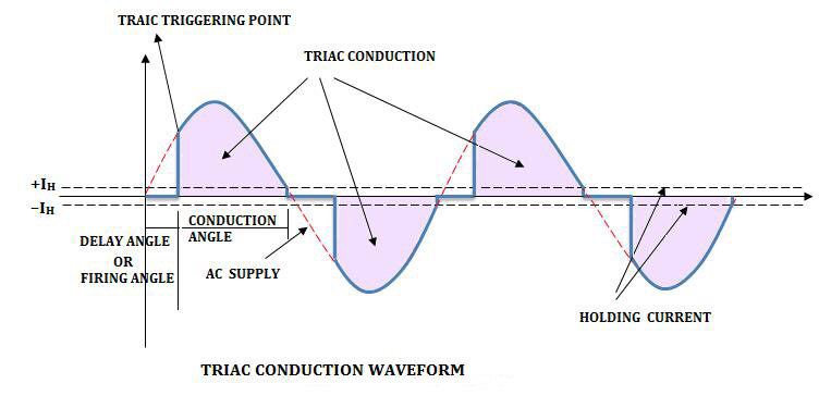
This is a three-terminal, four-layer, bi-directional semiconductor device that controls AC power. it can conduct in both the direction that means whether the applied gate signal is positive or negative and it passes the current in forward and reverses biased condition, it will conduct. so this device is used as a switch in the AC circuit. Pin 2 is input and MT1 is Output pin and pin 3 is gate. In general terms, we only know here that the TRIAC can be turned on by applying a pulse on the gate terminal. It can be triggered by the positive or negative polarity of gate pulses.
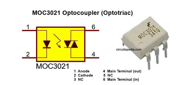
MOC3021 Optoucoupler –
Here MOC3021 optocoupler IC is used to trigger the Triac BT136. Pin no 6 of this optocoupler ic is used as input AC and pin 4 as output that goes directly to Gate terminal of Triac BT136. This optocoupler is actually optometric which triggered by the internal IR LED in this ic. Internal IR LED works as the DIAC that provides a pulse to the gate of optometric for Turn ON. The reason behind using the optocoupler is isolating the DC controller from the AC, Means there is no physical contact between Ac and Dc.
IR Decoding of Remote
copy and paste the following codes to Arduino IDE. Now upload and open the Tools – Serial Monitor. Take the remote to your hand in front of IR receiver and Press the buttons of remote which you want to set for ckt operation. you can see on the serial Monitor some decoded values present in numbers forms. You Can find this code in Arduino IDE in Examples.
#include <IRremote.h>

int RECV_PIN = 4;

IRrecv irrecv(RECV_PIN);

decode_results results;

void setup()
{
  Serial.begin(9600);
  // In case the interrupt driver crashes on setup, give a clue
  // to the user what's going on.
  Serial.println("Enabling IRin");
  irrecv.enableIRIn(); // Start the receiver
  Serial.println("Enabled IRin");
}

void loop() {
  if (irrecv.decode(&results)) {
    Serial.println(results.value, DEC);
    irrecv.resume(); // Receive the next value
  }
  delay(150);
}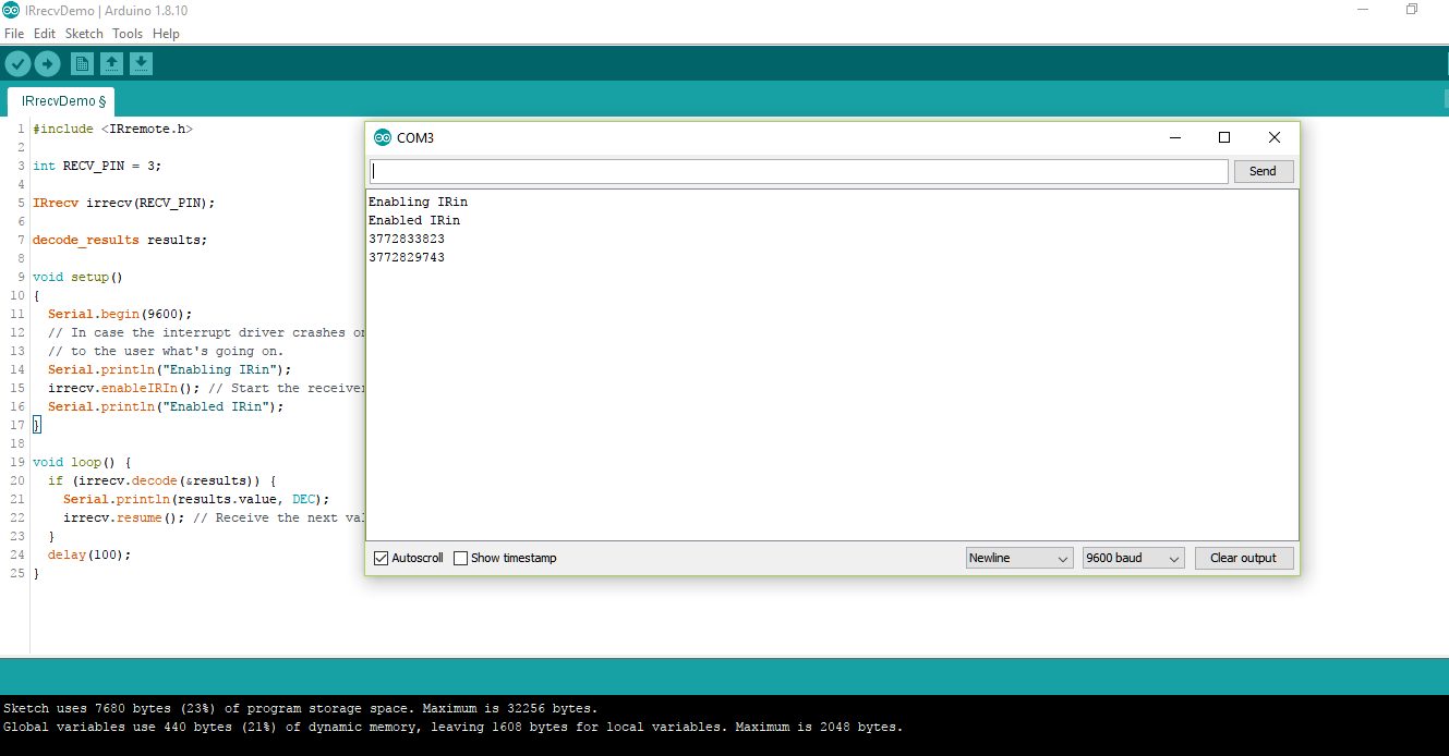
decoded value of other button and other remote may vary
Save that values for next dimmer programming.
Now copy and paste the code given below and your AC dimmer circuit is ready for use.
#include "IRremote.h"

int receiver = 4;
IRrecv irrecv(receiver);
decode_results results;

#include <TimerOne.h>
volatile int i=0;               // Variable to use as a counter
volatile boolean zero_cross=0;  // Boolean to store a "switch" to tell us if we have crossed zero
int AC_pin = 6;                 // Output to Opto Triac

int dim2 = 0;                   // led control
int dim = 128;                  // Dimming level (0-128)  0 = on, 128 = 0ff
int freqStep = 75;    // This is the delay-per-brightness step in microseconds.

void setup() {
  irrecv.enableIRIn(); // Start the IR receiver (classic remote)
  pinMode(AC_pin, OUTPUT);                          // Set the Triac pin as output
  attachInterrupt(0, zero_cross_detect, RISING);    // Attach an Interupt to Pin 2 (interupt 0) for Zero Cross Detection
  Timer1.initialize(freqStep);                      // Initialize TimerOne library for the freq we need
  Timer1.attachInterrupt(dim_check, freqStep);
}

void zero_cross_detect()
{
  zero_cross = true;               // set the boolean to true to tell our dimming function that a zero cross has occured
  i=0;
  digitalWrite(AC_pin, LOW);
}
// Turn on the TRIAC at the appropriate time

void dim_check()
{
  if(zero_cross == true) {
    if(i>=dim) {
      digitalWrite(AC_pin, HIGH);  // turn on light
      i=0;  // reset time step counter
      zero_cross=false;    // reset zero cross detection
    }
    else {
      i++;  // increment time step counter
}}}


void translateIR() // takes action based on IR code received
{
  switch(results.value)
  {
  case 3772829743:
    {

    if (dim<127)
   {
    dim = dim + 5;
    if (dim>127)
    {
      dim=128; // in vechiul sketch era 127
    }
    }}

    break;

  case  3772833823:
    {

      {
  if (dim>5)
  {
     dim = dim - 5;
  if (dim<0)
    {
      dim=0;  // in vechiul sketch era 1
    } }}}
    break;
  }}

void loop() {
 if (irrecv.decode(&results)) // have we received an IR signal?
  {
    translateIR();
    irrecv.resume(); // receive the next value
  }

}


Video
