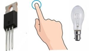
Touch Touch sensitive doorbell Alarm switch circuit
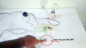
When the touch metal then the Alarm is switched ON and when Leave the finger from the touch plate then the Alarm is Automatically Switch OFF. This is very simple and easy because only three transistors and some other components are used. No IC is required for this Project.
Using this circuit, you can change the Old Experience of the Doorbell Switching method and can create a new high-tech Method With an Automatic Touch Doorbell Alarm Switch System.
Assemble the circuit as given in fig. Capacitor value can be between 2.2uf to 100uf. Be careful with the transistor terminal when constructing the circuit.
This Automatic Touch Doorbell Alarm Switch is very sensitive to human fingers, and this is very simple to construct. No IC is used in this circuit. At first when the Power is switched on in circuit, then switch remains OFF. When any touches the touch plate, then transistor Q1 is triggered, and as Q1 gets on, the transistor Q2 is also turned ON.
Q2 is PNP transistor, and the Emitter of this transistor is directly connected to the Positive supply. As this transistor turns ON, the Positive supply voltage is passed through Emitter to Collector of Q2. Therefore, the voltage goes to the Base of Q3 transistor through R4, and transistor Q3 turns ON and connects load with this transistor Collector gets a negative supply and completes the circuit and gets Turn ON.
You can connect a 9v Relay with transistor Q3 for More Power loads like an AC bulb. This circuit is tested on the breadboard as a given diagram.
If you want to make this circuit to remain connected, Alarm ON for a fixed duration of some seconds, then change the capacitor of 220uf Elase to use 10uf capacitor. With the 10uf capacitor, the time duration to automatic switch OFF is very less, about 1 sec. So with a Less valued capacitor, this touch alarm switch is working as in astable mode like the Push button with no delay to return to the original state.
This is a very interesting and effective Project for beginners. Use any small piece of any metal for making of touch plate.
Note- Pin Of BC 558 is the same as BC547
Also read Clap operated Switch circuit


Thank you so much dear!custom essay writing
How does it work? Regarding the voltage going to the base of Q1. Is a human finger typically positively charged relative to the environment?
Good question
When touch the touch metal then transistor get a noise signal(supply) from finger through base and then Q1 get About to turn ON (not fully turn ON) and after that the a negative supply passed through C of Q1 to base of Q2 and therefore Q2 will ON and Q3 also ON According to supply given by Q2 .
Pliz sir kind send me all detail about this circuit in this email id- vtk7676@gmail.com
Hi, Aman Bharti I very inspired from your website. You give amazing content and give detail knowledge about the project.
Sir can I get the values of output current (Ic) and input current (Ib).
Pingback: Simple electric circuit diagram, Electronic Circuit diagram for beginners