Touch Alarm
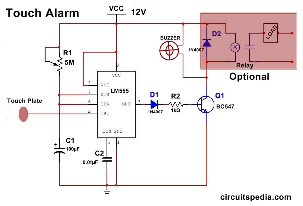
This is a simple but interesting Project. In this circuit 555 timer is used. 555 timer ic is connected in Monostable mode. A Very high resistor is connected between Vcc and pin 7 .
When touch the pin 2 then it is Triggered by the body because it get a negative pulse by touching it. When touch the pin 2, the output at pin 3 will remain High for a fix duration. After a set duration output gets Low Automatically.
When Touch the Touch plate, which is directly connected with pin 2, then output get High and Transistor Turned on and Alarm is played for some duration and after some duration automatic it will switched off.
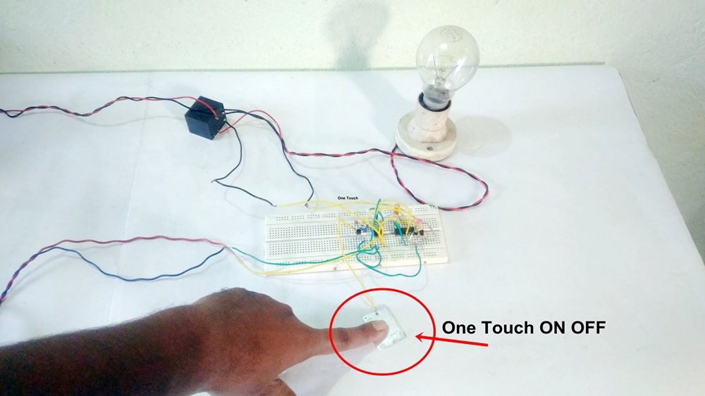
Sensitivity set by preset adjusting Any Power load can be connected by using a relay with transistor as shown in fig.
This circuit is more useful in Doorbell, Buzzer Alarm, Toys and some other Applications. The touch plate is made by any small surface of Metal.
The timing of output depends on the value of capacitor C1 and resistor R1. T=1.1R1 x C1
Components
NE555 IC-1
Capacitor
100uf 25v-1
0.01uf-1
Transistor
BC547-1
Resistor-
1K-1
Preset 5M or more -1
Diode
1N4007-1
OPTIONAL
Relay 12v 2A-1
Diode-1


