Contents
- LED flasher circuit using transistor
- Battery level indicator circuit diagram
- Mini Fm transmitter circuit up to 50M range
- contactless electric line tester
- overheat or temperature sensor
- Power on Delay timer
- ON-OFF using a single Pushbutton/Latch circuit
- DC Motor Direction Controller Forward and Reverse
- The blown fuse indicator circuit
- 230v Live wire scanner/tester
The following electronic circuit diagrams very Simple, useful, and can be made by any beginner.
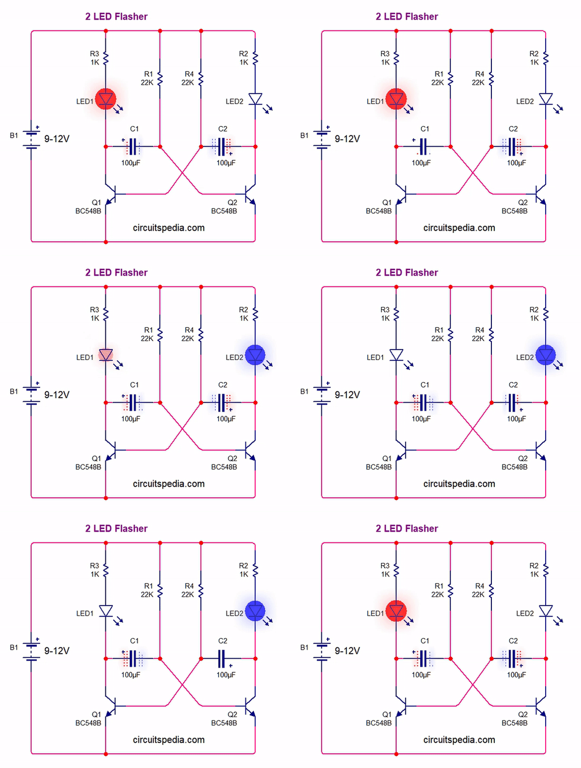
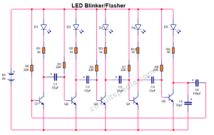
LED flasher circuit using transistor
Battery level indicator circuit diagram
Mini Fm transmitter circuit up to 50M range
contactless electric line tester
detect the line when the sensor wire touched over the cover of wire
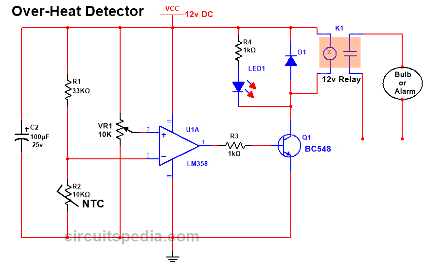
overheat or temperature sensor
Adjust the preset to what level of temperature you want to automatically detect. You get a signal from the buzzer when cross the heat to a fixed level. This circuit can be used in an automatic controlling circuit to prevent a device to damage from overheating.
This circuit consists of an LM358 comparator ic that makes this highly sensitive. By using an NTC (negative temperature coefficient) comparator ic gets a signal to make its output High.
Working of the circuit– NTC thermistor is a type of resistor but this has special properties, When the temperature of NTC thermistor will increase, the resistance will decrease and when the temperature will decrease the resistance of it will increase. At the normal temperature, the resistance of NTC has high so the high voltage signal will go at the pin of 2 because of voltage will not be dropped by the flowing with the ground as the NTC has high resistance. In this case, the voltage at pin 2 is HIGH and at pin 3 will be LOW as compared with pin 2 voltage. But when the temperature of NTC will increase then the resistance of this thermistor will LOW and the maximum voltage will pass across this to the ground and pin 2 gets LOW as compared with pin 3 and the voltage level at the pin will go HIGH. As the properties of the comparator when the voltage signal at the non-inverting pin is HIGH then the output of the comparator is HIGH. So the output will now be High and the base terminal of the transistor will get a high signal and now the transistor will turn on and also connected Relay will activate and the load will activate also.
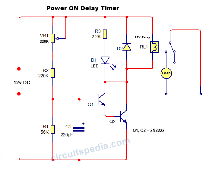
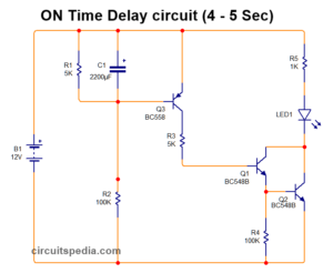
Power on Delay timer
This is very useful to prevent a device from sudden unregulated voltage spikes or surge currents. you can change the delay time duration by changing the value of capacitor C1. When a 220uf capacitor is used duration of delay is about 5 – 8 seconds.
This circuit Turns the Load ON or OFF by pressing a single pushbutton switch. 1st time pressed the pushbutton switch- The load is ON. 2nd time pressed the pushbutton again Turn OFF the load. A MOSFET IRFZ44N and some common components are used in this circuit. Use a Relay of 9v if using a 9v power supply to connect the load.
DC Motor Direction Controller Forward and Reverse
Turn on the DC motor in both directions Forward and Reverse using two separate pushbutton switches. One pushbutton is used for forward and a second pushbutton is used for the reverse direction. But during the release of the pushbutton motor will stop. Only when the pushbutton is pressed motor start to move. But if want to move the motor continuously in any direction then you can use a two-way switch and the common pin of that two-way switch is connected to the positive of the battery. In this circuit, Only one DPDT (Double Pole Double Throw) Relay and two Pushbutton switches are used.
The blown fuse indicator circuit
When the fuse has blown or burns the LED1 and LED2 are starting to glow. But in the case of the fuse is not burning then LED3 and LED 4 will glow. The capacitor 104j 400v(o.1uf) is connected with a 100 Ω resistor, this is for the protection of LEDs and this is optional.
230v Live wire scanner/tester
This is another electric tester circuit that detects the signal from touching the sensor wire over the cover of wires. Use only Battery for this circuit.
Also Read
-
Delay on timer circuit using transistor
-
Touch switch circuit for doorbell without ic
-
DC short circuit Autocut without ic
-
Touch Switch For ON And OFF Using 555
-
Dark Sensor Circuit
-
Single Touch ON OFF Switch Using 555 And 4017
-
What is Opto-coupler/opto-Isolator

