All You Need To Know About The Concept Of PCBA
Contents
What is PCBA
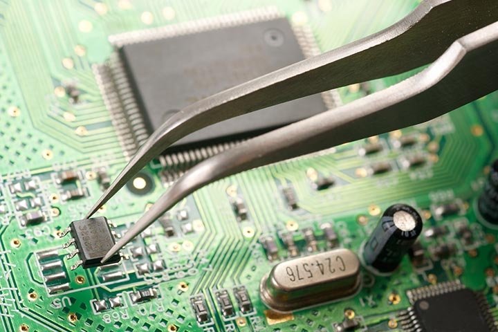
Before examining what aspects should be kept in mind while purchasing a PCBA, it is necessary to understand what PCBA is? Furthermore, PCBA is short form of PCB assembly, The manufacturing Process of PCB is called PCBA. In the PCB assembly process, All the necessary components and parts are mounted on the printed circuit board for the making of deployment of desired purposes. PCBA or printed circuit board assembly consists of several components that are assembled on a panel, like:
- Capacitance
- Resistance
- IC
- Connector
The Use Of PCBA
PCBA is located in almost every electronic gadget and machine, from cell phones to PCs, microwaves, and large vehicles, like trucks and cars, etc. It is a fundamental piece of everything that needs the power to work. Subsequently, you should understand the reason for its significance before thinking of purchasing a PCBA.
An operative PCB configuration is substantial as it aids in decreasing errors or some short-circuit. A promising design sorts out various wires joined because nobody wants a scrambled wreck. As the great printed circuit board assembly is a fundamental piece of hardware, it contributes significantly to the entire globe’s technological advancement. That’s the reason that a promising assembly is vital to stop and prevent different mishaps.
Some Factors To Consider While Buying PCBA
Now, this is clarified what a PCBA is. A further reason for knowing its significance is that the time has come to continue with the advice to remember while purchasing any PCB assembly. While purchasing it, it is vital to consider the material and the type of the mountings. At the point when an electronic gadget is assembled, some factors are considered, which are mentioned below:
- Managing space
- Warmness
- Aids of accessibility are high
- Rate
- Conductivity
So, when the time comes to be fitted in the circuit board, you need to look at its procedure and the material utilized to manufacture and further develop. Before buying it, try freeing of cost samples and quickly finding your solution to your appliance. Plus, keep in mind the use of the complimentary samples, and search for the kind of available mounting and the material utilized for the great PCB assembly.
Categories of Mounting
Few Categories of Mounting
Presently, there are numerous sorts of mounting categories, which are as follows:
- Threaded Mounting
In threaded PCB form, there are 3 basic types, basic is a standard that is held in one spot with a single nut, providing a secure fit that can be opened and again fixed. Then, at that point, we possess the safer undercut as it is set into the string. Ultimately, we have self-tapping. This kind of mounting does not require any kind of washer or even a nut because it is adjusted with a self-tapping thread.
- Snap-fit Mounting
It lifts onto a board or frame hole and fixes areas of strong mounting, making it more simple for installment. Three kinds of these fits are:
- Edge lock
- Knife
- Fir tree
- Snap-Locking Mounting
It impulses onto the panel and simply can be delivered without any problem.
- Press Fit/Blind Hole Mounting
This is a reasonable mounting type for space-limited applications. Their blade-like edges hang on firmly to the binding holes, rendering them fixed in one hole.
- Adhesive-Based Mounting
This type of mounting doesn’t need a mounting hole, conserving duration and exertion.
By utilizing this list of mounting classifications, you can recognize and have no trouble picking what kind of mount you need for your circuit board. Indeed, you will also know about the application is where the circuit will fit into. As the mounting categories are discussed above, now is the ideal time to look at the material.
Types Of PCBA
Below are two different types of circuit boards:
- Complex and rigid type PCB
- Flexible and soft type PCB
Development Process Of PCBA
There are two sorts of development strategies utilized for the PCB assembly.
- Through-Hole Development: Component leads are embedded into the holes.
- Surface-Mount Development: Components are put on land or pads on the external surfaces of the PCB.
In any case of both development types, the part leads are still electrically and precisely fixed to the PCB with molten metal solder.
The volume of boards to be assembled will decide how the parts will be welded. If it is for a high creation volume, joining components to the Printed Circuit Board is best finished by machine placement. Machine placement is completed with mass wave soldering or reflow ovens. If the production amount is for little volume models, welding by hand turns out only great as a rule (Ball Grid Arrays are challenging to bind manually).
Frequently, through-hole and surface-mount development must be acted in one PCB assembly since a few required electronic parts are accessible in through-hole packages. In contrast, others are just accessible in surface-mount bundles. Likewise, it is a valid justification to utilize both techniques during a similar assembly because through-hole mounting can give more solidarity to the electronic parts that will probably go through some physical stress.
If you realize that your PCB won’t go through any actual pressure, it might be wiser to involve surface-mount strategies to occupy less room on your board.
After the parts have been entirely built on the PCB assembly, it is best to test to ensure that the board works accurately and at the performance required. Here is a portion of the manners they try after they have been assembled.
- A detailed visual inspection to ensure that no electrical parts are out of place on the circuit board. It is likewise great to always check the soldering when the power is off.
- Analog Signature Analysis: when you apply a current-limited AC sine-wave across two places of the electrical parts and circuit. (Power is off)
- Performing an In-Circuit Test: checking different physical estimations within the board, like the voltage, frequency, and so on. (power is on)
- Performing a Functional Test: checking that the circuit board does what it is planned for. (Power is on)
Wrapping Up!
If a portion of the printed circuit boards fails any of the above tests, not everything is lost. You can find out where the issue is occurring and supplant the weak parts or potentially board to consider it to pass. This is once in a while alluded to as reworking.

