LED chaser circuit
1. LED Running Effect Without IC
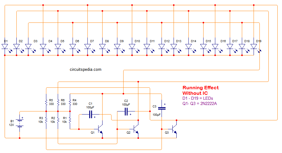
Here is presenting a circuit diagram of LED chaser . The Main Advantage of this LED chaser is it does not require any ic or microcontroller.
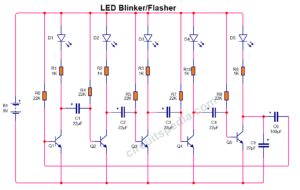
This Circuit is made using mainly NPN transistors and capacitors and some resistors.
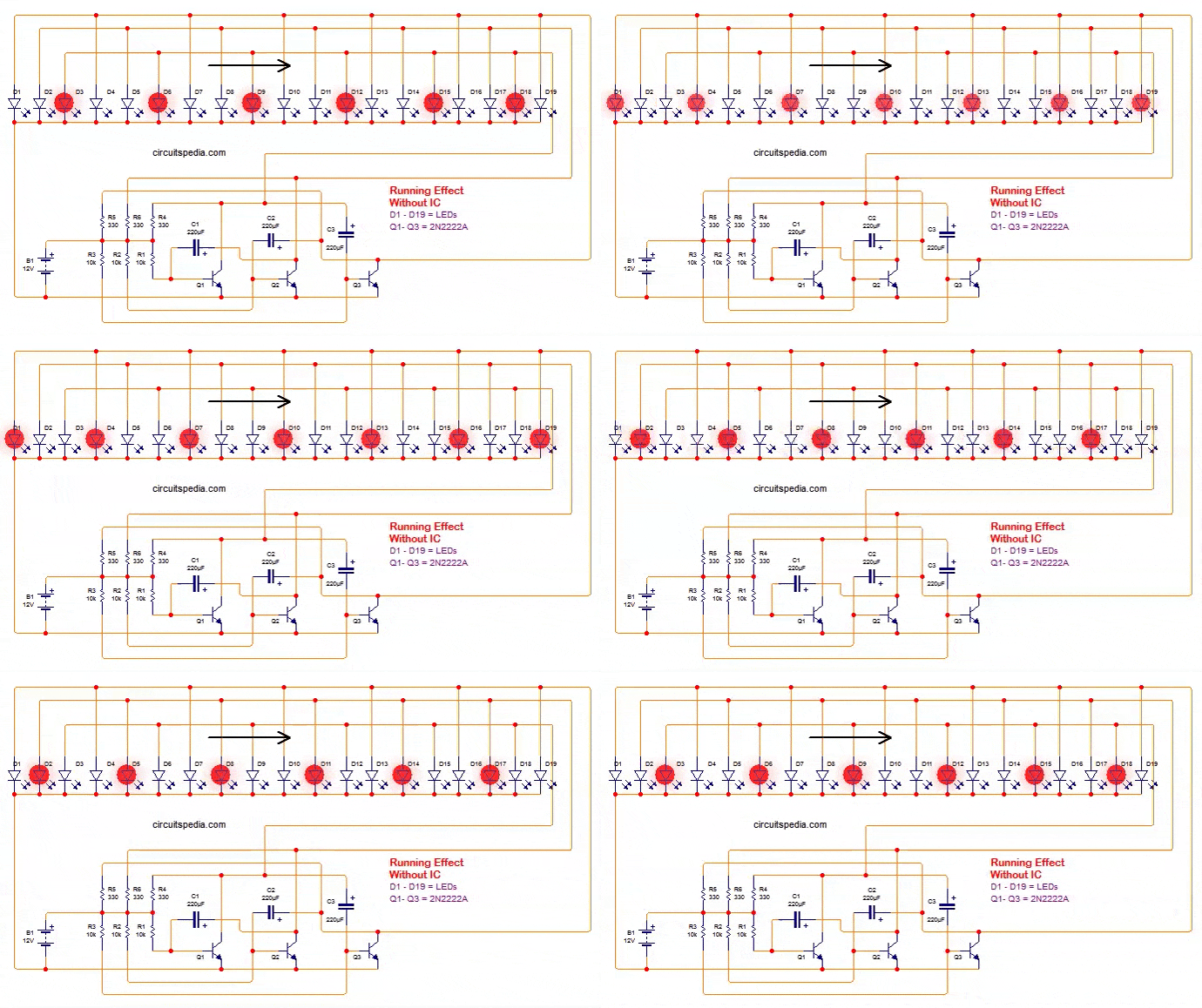
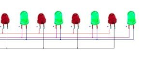
This LED chaser circuit produces a blinking effect that looks the same as Running effect in a particular direction. All LEDs blink as moving in one direction. We can also say that this is an LED running effect chaser circuit.
This is an easy circuit and it can easily construct at home by even who beginner in this field.
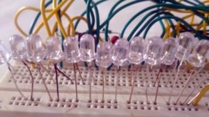
There are 19 LEDs are connected in this circuit in A straight line. But You can connect in different shapes like circle, Heart shape, Arrow shape Etc.
If you want to connect Ac light at the place of LEDs then need to modify the circuit using TRIAC and Optocoupler.
Circuit diagram
Components
LED – 19 pc
Transistors 2N2222A – 3 pc
Resistors
10K – 3 pc, 330 Ω – 3
Capacitors 220 uf or 330 uf (for slow speed) – 3 pc ( 100uf for high speed )
12v battery or any dc source
LED chaser circuit
2 . LED Running effect using IC 74HC595 and 555
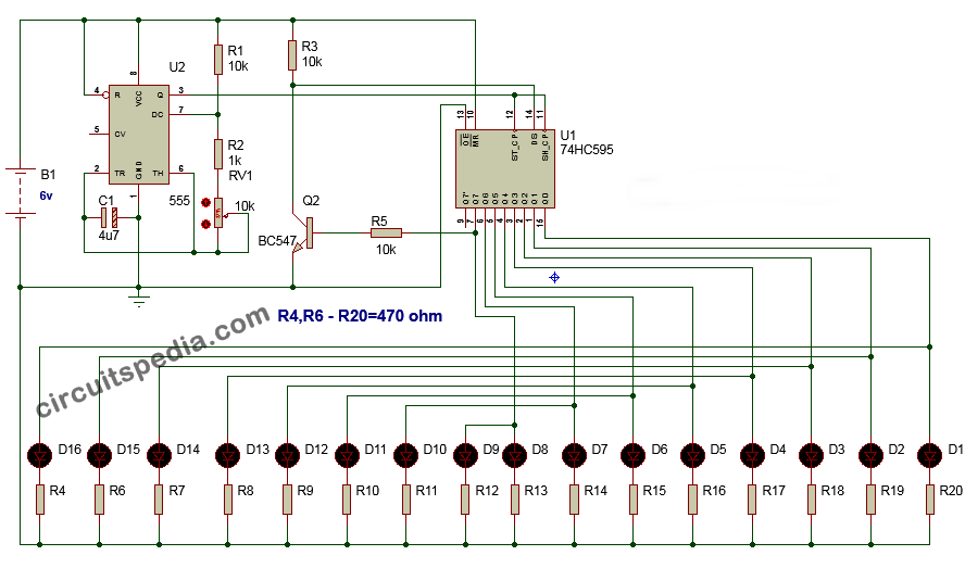
This running effect circuit made using shift resistor ic 74HC595 and 555 timer. Use the 9v dc supply for this circuit. The speed of running can be controlled using the preset RV1. By adjusting the 10k preset the pulse of oscillation of 555 timer ic can be adjusted and according to pulse rate at pin no 3 the blinking or running effect of LEDs controlled.
circuit diagram
Components
IC
555 – 1
74HC595 – 1
Transistor BC547 -1
Preset 10k -1
Resistors
10k – 3
1k -1
470 R – 16
Capacitor 4.7uf – 1
LED (Red or Blue) – 16






What range of voltages would the transistor only version run on? Would the resistors need changing to run on 6V? The LEDs I will be using have forward voltages of 2.5-3.5V
you should try to check minimum 6v DC
This LED chaser circuit is a fantastic project! The diagram is very clear, and I love how you explained each component’s role. I can’t wait to try building this with some friends. Thanks for sharing!
Great post! I love how you’ve explained the LED chaser circuit step-by-step. The circuit diagram is really clear, and the tips on choosing the right transistors were super helpful. I can’t wait to try building this on my own! Thanks for sharing!
This LED chaser circuit is fantastic! I love the visual effect it creates, and your detailed explanations make it easy to understand. I can’t wait to try building it myself. Thanks for sharing the circuit diagram!