LDR circuit diagram
Dark sensor circuit
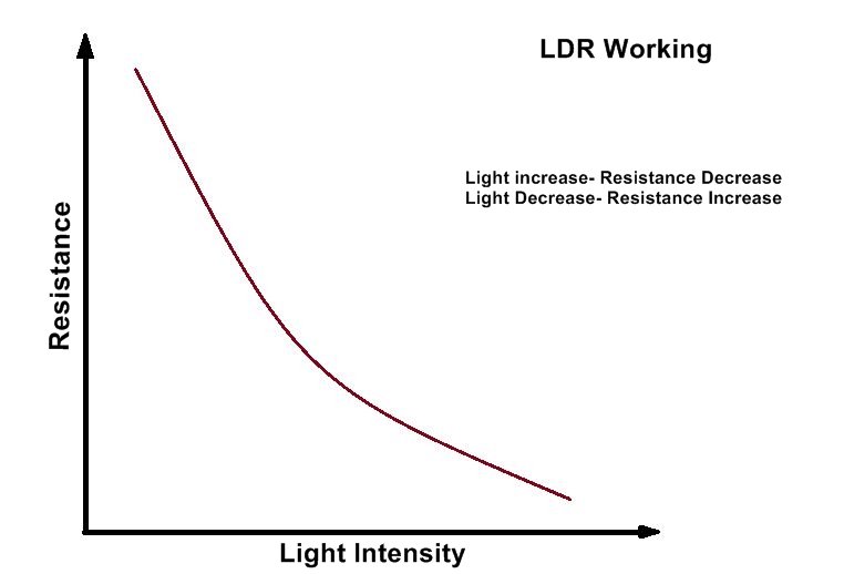
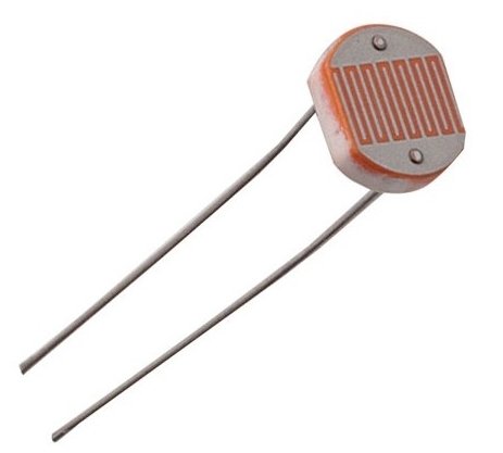
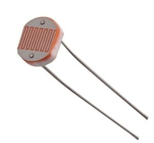
This is a light-controlled LED light Dark sensor circuit, a Light-activated switch, which fully depends on Light. LDR is used in this for sensing the DARK and LIGHT. LDR is a Light Dependent Resistor, which resistance increases in darkness and its resistance is Decreases when Light falls on it.
Automatic street light circuit
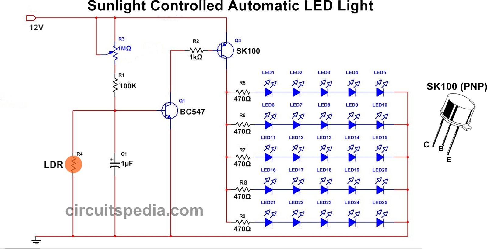
In this circuit, 25 high-bright white LEDs are used, and each Row of the series connection has 5 LEDs in it. 5 LEDs in one Row and as this here total 5 series arrangements are connected and in one series only 5 LED connected.
Working
LDR (Light Dependent Resistor)
- Changes its resistance based on the amount of light falling on it.
- High resistance in the dark and low resistance in bright light.
BC547 (NPN Transistor)
- Acts as the first stage of control.
- Its switching is determined by the voltage at its base, which depends on the LDR and the associated resistor network.
SK100 (PNP Transistor)
- Provides power to the LED array from the 12V supply.
- It is switched on or off by the BC547’s output signal.
Resistors
- R1 (1 MΩ) and R2 (100 kΩ) form part of the voltage divider that sets the operating point for the LDR and BC547.
- R3 (1 kΩ) is typically a current-limiting/base resistor for the BC547.
- Each LED has its own series resistor (470 Ω) to ensure correct current flow from the PNP transistor.
Capacitor (C1, 1 µF)
-
-
Often included to stabilize the switching or provide a slight delay, preventing rapid on/off flicker around the threshold.
-
LED Array
- Multiple LEDs, each with its own 470 Ω resistor, are connected in parallel.
- Powered by the SK100 transistor’s emitter when it is turned on.
12V Power Supply
-
-
Provides the main DC voltage source for both the control circuitry and the LEDs.
-
Basic Circuit Operation
Bright Light (Daytime) Condition
LDR Resistance is Low
- With plenty of ambient light, the LDR’s resistance drops significantly.
- This changes the voltage divider formed by the LDR, R1, and R2, resulting in less voltage at the base of the BC547 transistor.
BC547 Stays Off
-
-
Because its base does not reach the required threshold to forward-bias it, the BC547 remains non-conducting.
-
SK100 (PNP) Also Off
- In a PNP transistor, you need the base to be pulled to a lower potential than the emitter for conduction.
- When the BC547 is off, it effectively allows the SK100 base to stay at a higher potential, so SK100 remains off as well.
LEDs Remain Off
- No current flows to the LED array because the SK100 emitter does not supply power.
- The circuit conserves energy in bright conditions.
Dark or Low-Light (Nighttime) Condition
LDR Resistance Increases
- In low light or darkness, the LDR’s resistance rises sharply.
- This causes a shift in the voltage divider output, raising the base voltage of the BC547.
BC547 Turns On
- Once the base voltage is high enough, the BC547 switches on and conducts from collector to emitter.
- This effectively pulls the base of the SK100 transistor toward a lower potential (closer to ground).
SK100 (PNP) Switches On
- A PNP transistor conducts when its base is at a lower potential than its emitter.
- Because the BC547 is now pulling the SK100 base low, the SK100 emitter-to-base junction is forward-biased.
- The SK100 transistor saturates, supplying current from the 12V rail out through its emitter.
LEDs Illuminate
- With the SK100 on, the LED array receives current from the 12V supply.
- Each LED has a 470 Ω resistor in series to set a safe operating current.
- The LEDs light up and remain lit as long as it is dark.
Circuit Construction Highlights
LDR and Resistor Setup
-
-
The LDR is placed in a voltage divider with high-value resistors (1 MΩ and 100 kΩ) to ensure the transition between on/off is noticeable and to minimize current consumption.
-
Two-Transistor Configuration
- The NPN (BC547) is used as a switch that detects the LDR’s voltage changes.
- The PNP (SK100) handles the higher current for the LEDs, preventing the BC547 from needing to handle large loads.
Capacitor for Stability
-
-
The 1 µF capacitor (C1) helps to filter out quick changes in light level or power fluctuations, reducing flicker or chattering around the threshold.
-
Parallel LED Strings
-
-
Each LED has its own 470 Ω resistor. This ensures consistent current sharing and prevents one LED from hogging the current.
-
12V Supply
-
-
A standard 12V DC supply (e.g., battery or adapter) is enough to power multiple LEDs, making the circuit suitable for low-voltage lighting applications (like in gardens, hallways, or decorative setups).
-
Step-by-Step Summary of Operation
-
During Daytime
-
LDR has low resistance → BC547 base is not driven → BC547 is off → SK100 is off → LEDs are off.
-
-
Transition to Night
-
LDR resistance rises → base of BC547 gets enough voltage → BC547 turns on → pulls SK100 base low → SK100 conducts.
-
-
Nighttime
-
SK100 feeds the LED array from 12V → LEDs glow.
-
-
Return to Day
-
LDR resistance drops → BC547 loses base drive → BC547 off → SK100 off → LEDs off.
-
Practical Tips and Adjustments
Sensitivity Control
-
-
If the circuit includes a potentiometer (100 kΩ in the diagram) in series with the LDR, you can tweak it to decide the exact light level at which the LEDs turn on.
-
Component Ratings
- Ensure the transistors can handle the total current for all LEDs.
- Check each LED resistor is sized properly (470 Ω typically works for a 12V supply with standard LEDs).
Placement of LDR
-
-
Mount the LDR in a location where it accurately senses the ambient light level (e.g., near a window or outdoors in a waterproof enclosure).
-
Power Source
- A stable 12V DC adapter or battery is recommended.
- If using a battery, monitor voltage levels to avoid excessive discharge (if rechargeable).
Expandability
-
-
You can add more LED + resistor strings in parallel if your power supply and SK100 transistor can handle the extra current.
-
Assemble the circuit in any general-purpose PCB, and LDR should set as the light falls directly on it. Give 12 v DC Supply.
Components
SK100 Transistor – 1
BC547 Transistor – 1
Preset 1M – 1
100K resistor – 1
1K resistor – 1
1uf capacitor – 1
Another good working circuit
Circuit 2
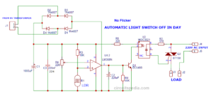
Automatic ON-OFF light switch circuit
This is a light-operated Relay circuit. Light Dependent Resistor(LDR ) is used to operate the switching Function of this circuit. This circuit is used to Switched on light At night Automatic and switch OFF in DAY light (sunlight) Automatic. There is no need to switch it on or off manually.
When Light is falling on LDR, the Bulb is OFF, and at night, when there is no light incident on LDR, the Bulb switches on automatically.
Transformer 9-0-9 – 1
Bridge rectifier ic or 1N 4007 diode – 4+1= 5
Resistor 1K- 2, 220k – 2
preset -470k – 1
Transistor BC557 (PNP) – 1
BC547(NPN) – 1
Zener diode 8.2v (500ma) – 1
Regulator IC 7806 – 1
Relay 6v – 1
LDR – 1
LED – 2
Also read
- Fan regulator/AC dimmer circuit
- Melody generator/ Door bell alarm
- Switch ON Delay Timer circuit
- Arduino projects for beginners
- What is Opto-coupler




Pingback: How Transistor Works as Switch. NPN and PNP transistor working