Light sensor circuit
Shadow detector
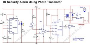
A Buzzer beeped and led will glow for a fixed time when a shadow falls on a phototransistor. This is a very sensitive light-sensitive circuit operated using the 741 opamp ic and 555 timers. Here 741 ic is connected as a comparator which compares the voltage at the input. It is able to detect the moving shadow in dim light, so it is very useful for protection or security purpose. 555 timer is connected as Monostable mode to getting for a fixed delayed output.
The input is connected with the inverting terminal of the comparator, In normal light, the phototransistor is in ON state and the voltage of pin 2 is Lower than pin 3, in this case, the output of the comparator will Remain HIGH and the led connected with the comparator output will glow. During this case, the trigger pin 2 of 555 timer does not get a trigger signal and the final output of 555 at pin 3 is LOW and Buzzer is Not Beeping. (Pin 2 of 555 is only triggered LOW or V).
But when the shadow falls on the phototransistor, This will turn OFF and the current directly pass through the 100K resistor to the inverting terminal. The voltage of pin 2 (inverting) of the comparator goes high and the output of the comparator goes to LOW. As the output of the comparator goes low the pin 2 of 555 timer get triggered and the output of 555 at the pin will go HIGH and the buzzer beeped and LED (D2) glow for a fixed duration and after some moment automatic off. The timing of the buzzer beep can be changed by adjusting the variable resistor RV2.
Adjust variable resistor VR1 (47k) until LED D2 stops glowing and the buzzer stops beeping while LED1 glows. This is the position of VR1 to be maintained for that particular intensity of light. LED1 will continue to glow even when a shadow is detected. The circuit can be assembled in a cabinet and make a 5mm hole in front of the phototransistor.
Op-amp μA741 (IC1) is used as a voltage comparator. The non-inverting input of IC1 gets a controlled voltage from potential divider R2 and VR1.
Components
IC
555 – 1
741- 1
Phototransistor sensor –
L14F1 – 1
resistors
10k – 2
4.7k- 1
100k – 1
220Ω – 1
1K- 1
Preset- 47K -1, 500K -1
capacitor
47uf 25v- 2
0.01uf – 1
LED-2
Buzzer (9v)- 1
Also read
-
Dark sensor circuit (4 circuit)
-
IR Based Security Alarm Circuit
-
Infrared proximity sensor circuit
-
What is Opto-coupler/opto-Isolator
-
Logic gates (AND, OR, NOR, NAND)


