What is a Zero crossing detector
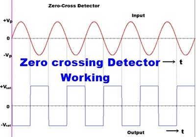
Zero crossing detector detects how many times the input signal crossed the Zero value or zero voltage level. Zero cross detector is basically a comparator circuit that compares the input sinusoidal signal or Sine wave signal with the zero voltage level. In other words, we can say that this detects the voltage changing from a positive level to a negative level and negative level to positive level. The output of the zero-cross detector changes when the input voltage crosses the zero level to High or High to zero.
A Zero cross detector compares the input signal with the zero reference voltage (Vref). It changes the output either +Vsat or –Vsat by switching from LOW to HIGH or Vice versa. When the input crosses zero reference voltage. When the input voltage signal is even a little higher or Lower than 0v, the output will quickly change. A zero-crossing detector can be made using a general-purpose operational-amplifier, Using optocoupler or using transistors.
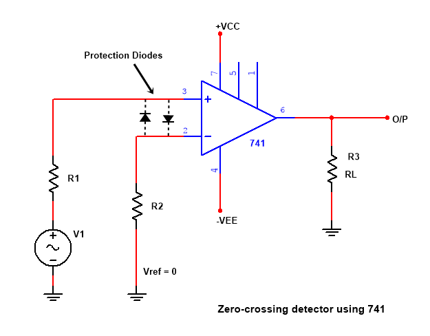
Zero crossing detector circuit using op amp LM741
NON-Inverting Zero cross detector
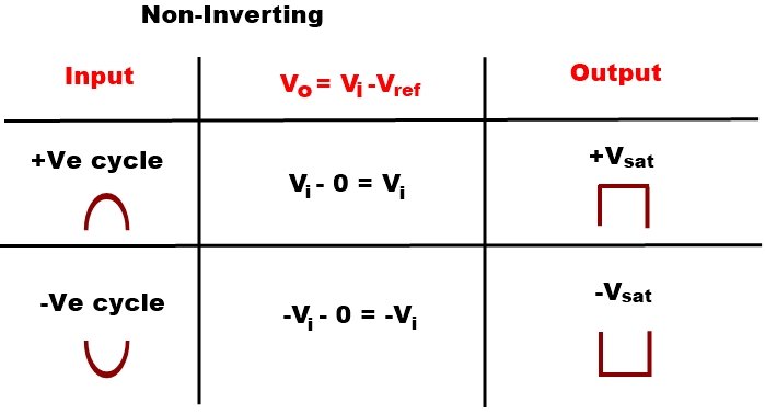
If Reference voltage zero is set on the inverting input terminal means the inverting terminal is grounded and the Input signal is applied at NON-Inverting terminal. +Vcc is connected with pin 7 and -VEE with pin 4, 6 is the output pin is and a load resistor RL connected with output to ground, even a little amount of input voltage in higher than zero (Reference voltage), then the output will HIGH. When the input goes on increasing from zero to positive, then the output voltage goes into Positive saturation.
The cross detector is also called a sinewave to square wave converter
This Output is called +Vsaturation.
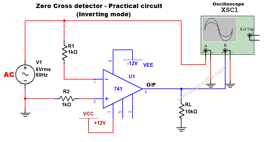
Inverting Zero Cross Detector
If input voltage is applied at the Inverting terminal and reference voltage are given on NON-Inverting terminal or the Non-inverting terminal is grounded, when even also a little amount of input voltage is higher than zero volts the output will switch to LOW. When the input goes on increasing from zero to positive, then the output voltage goes into Negative saturation.
And this LOW output is called –Vsaturation.
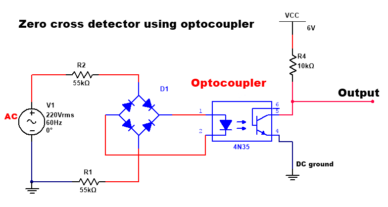
Zero-cross detector using optocoupler
In the circuit of the zero crossing detector using optocoupler, we used 1 full-wave rectifier and the positive DC supply of the bridge rectifier connected to the cathode pin of optocoupler input. The output is connected to the collector pin of the optocoupler. Here full-wave bridge rectifier is used without the filter capacitor. The emitter pin of the optocoupler is connected to the DC ground. VCC is connected with the collector pin. A resistor connected with a collector is also called a Pull-up resistor.
Uses of zero cross detector (ZCD)
- Triac and SCR Control: Zero-cross detectors are frequently used in circuits that control TRIACs (Triode for Alternating Current) and SCRs (Silicon Controlled Rectifiers). These semiconductor devices are often used for phase control in AC loads such as lamps, heaters, and motor speed controllers. By detecting the zero crossing of the AC waveform, the circuit can trigger the TRIAC or SCR at the precise moment to control the amount of power delivered to the load. This enables smooth and efficient control of AC power, allowing for applications like dimming lights or regulating heater temperature.
- Switching Power Supplies: In switch-mode power supplies (SMPS), zero-cross detectors help synchronize the switching of components like MOSFETs or IGBTs with the AC waveform. Synchronization ensures that the switching occurs at the zero crossing of the AC voltage, minimizing electromagnetic interference (EMI) and improving the efficiency of the power supply.
- Light Dimmers: Zero-cross detectors are crucial in light dimmer circuits, which control the brightness of incandescent bulbs or dimmable LED drivers. By detecting the zero crossing of the AC voltage, the dimmer circuit can trigger the TRIAC or other semiconductor devices to switch on or off at the appropriate phase angle. This allows for smooth and flicker-free dimming of lights.
- Audio Signal Processing: In audio applications, zero-cross detectors can be used for zero-crossing detection algorithms. These algorithms are used in audio processing tasks such as pitch detection, audio effect processing, and envelope detection. Detecting zero crossings helps in determining the timing and phase of audio signals, which is crucial for accurate processing and manipulation of sound.
- Data Communication: Zero-cross detectors play a role in synchronization and timing in AC-based data communication systems. They provide reference points for timing signals and ensure accurate detection of data bits transmitted over AC lines. This helps in maintaining synchronization between transmitting and receiving devices, especially in systems where data is transmitted using AC signals.
- Power Metering: In energy metering systems, zero-cross detectors are used to detect the timing of the AC waveform. This information is essential for accurately measuring power consumption and billing in AC systems. Zero-cross detectors provide the timing reference needed to calculate parameters such as power factor and total energy consumption.
- Microcontroller Interface: Zero-cross detectors provide a digital signal that can be easily interfaced with microcontrollers. Microcontrollers can use this signal for various control and monitoring applications, such as synchronizing operations with the AC mains, implementing time-based functions, or triggering specific actions based on zero-crossing events.
- ZCD as Phasemeter
- ZCD as Time Marker Generator
- Frequency Control and Measurement
- Audio and AC Signal Processing
- Light Sensing and Control
- Synchronization and Timing
FAQ (Frequently asked questions)- Zero Crossing Detector Circuit
Q: What is a zero-crossing detector circuit? A: A zero-crossing detector circuit is a type of electronic circuit that detects the point at which an alternating current (AC) signal crosses the zero-voltage reference.
Q: What is the purpose of a zero-crossing detector circuit?
A: The primary purpose of a zero-crossing detector circuit is to provide timing or synchronization information based on the zero-crossing points of an AC signal. It is commonly used in applications such as triggering circuits, phase control circuits, power control circuits, and digital communication systems.
Q: How does a zero-crossing detector circuit work?
A: A zero-crossing detector circuit typically uses a comparator or an operational amplifier (op-amp) along with resistors and capacitors. The circuit compares the AC signal to a reference voltage, typically the ground or a virtual ground, and produces a logic-level output when the AC signal crosses the zero voltage threshold.
Q: What are the components used in a zero-crossing detector circuit?
A: The main components used in a zero-crossing detector circuit include a comparator or op-amp, resistors, capacitors, and sometimes diodes for signal conditioning or protection.
Q: What are the common types of zero-crossing detector circuits?
A: Some common types of zero-crossing detector circuits include simple comparator-based circuits, op-amp-based circuits with hysteresis, and circuits using optocouplers or transformers for isolation.
Q: What are the applications of a zero-crossing detector circuit?
A: Zero-crossing detector circuits find applications in various areas, such as dimmer circuits, motor control circuits, audio and AC signal processing circuits, phase-locked loop (PLL) circuits, and frequency control systems.
Q: What are the benefits of using a zero-crossing detector circuit?
A: Zero-crossing detector circuits offer precise timing or synchronization information, enabling accurate control of switching events or phase-related operations. They help in reducing noise, improving power efficiency, and optimizing performance in many AC-based systems.
Q: Can a zero-crossing detector circuit be used for DC signals?
A: No, zero-crossing detector circuits are specifically designed for AC signals. They rely on the alternating nature of the signal to detect the zero-crossing points.
Q: Can a microcontroller or digital logic IC be used as a zero-crossing detector?
A: Yes, microcontrollers or digital logic ICs can be programmed or configured to function as zero crossing detectors. They can process the AC signal and generate a digital output based on the zero-crossing information.
Q: Are there any considerations for selecting components in a zero-crossing detector circuit?
A: Some important considerations include selecting appropriate comparator or op-amp specifications, choosing suitable resistors and capacitors for desired timing characteristics, and ensuring signal integrity and protection through proper conditioning and filtering techniques.
Also read
-
LOGIC GATES
-
Difference between Latch and Flip-flop
-
Sample and Hold Circuit
-
Arduino Remote control AC Dimmer
-
Zener diode working





interesting for a very long time
Of his works, he is especially famous
Thanks for the post