12v CFL Inverter circuit for Emergency Light
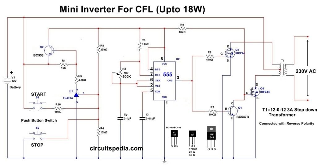
This is a small power inverter circuit that produces 230v ac at the output through the transformer. The circuit is designed by T.Kalpana. This can be used as the emergency CFL lighting, CFL needs AC input for operating and this circuit provides the AC to CFL. This circuit is very useful for home, shop, small place for emergency CFL light. This CFL inverter circuit is operated using the 12v Lead-acid battery which is mostly used in all homes. In this inverter circuit, a 555 timer ic is used which is connected in astable multivibrator mode, so it produces the continuously on-off signal, this on-off signal called a pulsed signal.
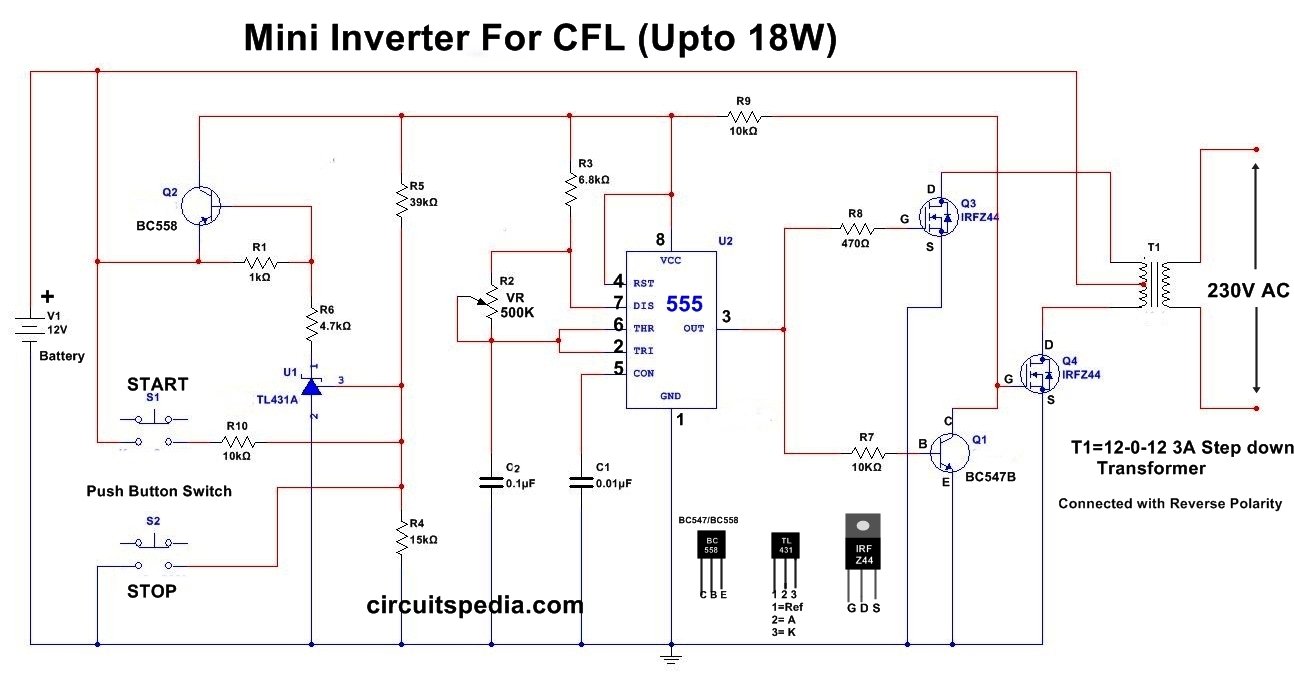
The preset is used to set the frequency at 50HZ. At the output of 555 timer ic, there are 2 resistors are connected, one is 470 ohm and the second is 10k ohm. The output signal follows two paths. One through the resistor to gate of MOSFET Q3 and second is through a transistor to the gate of MOSFET Q4.
Schematic diagram
Working
When the output of 555 timer ic is High, then the MOSFET Q3 flows the current to the primary winding coil of the transformer and Inducing High voltage AC at Secondary winding. Here Step down transformer is connected in reverse connection, it means the primary winding is connected here with output. When the output of 555 timer is low, MOSFET Q4 pulls out the current to the ground and inducing a voltage at the secondary winding. Mosfet Q3 and Q4 operate alternatively according to their gate voltage are switched on and off in a push-pull manner.
When switch s1 is pressed momentarily, CFL glow which is connected at 230v AC output terminal. When switch s2 is pressed momentarily then the CFL is switched off. TL431 used here for preventing the deep discharge of the battery . At low voltage, the circuit will automatically disconnect. The circuit produces an output voltage of approximately 230v. Use Separate heat sink with MOSFETs, and connect the transformer in reverse position.
Note – Careful with circuit operation. It may dangerous and chances of shock
Components
IC
555-1
Resistor
10k-3, 4.7k-1, 15k-1, 39k-1, 6.8k-1, 470 ohm-1
Transistor
BC558-1, BC547-1, TL431-1
MOSFET
IRF Z44-2
Capacitor
0.1uf-1, 0.01uf-1
Push button switch-2
preset -1 500k
Transformer 12-0-12 3A
Reference – electronics for you

