How transistor works
Transistor working simple
Transistor is a 3 Terminal electronic semiconductor component/device.
It has three terminals named a BASE, Emitter, And Collector.
Transistor name meaning lies in its own working.
Trans + istor = Transistor
The prefix trans tells about signal transfer from low resistance to high resistance part and istor means solid physical structure having the property of resistance.
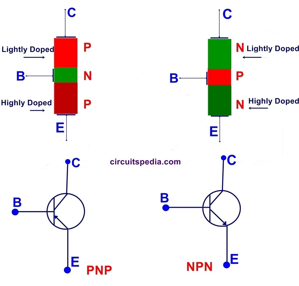
A transistor has 3 sandwich layers of doped semiconductors.
Basically, Transistors are 2 types.
1 . NPN Transistor
2. PNP Transistor
The transistor is the very important components in an electronics system. This is the basic electronic component that uses vastly in the making of the electronic circuits.
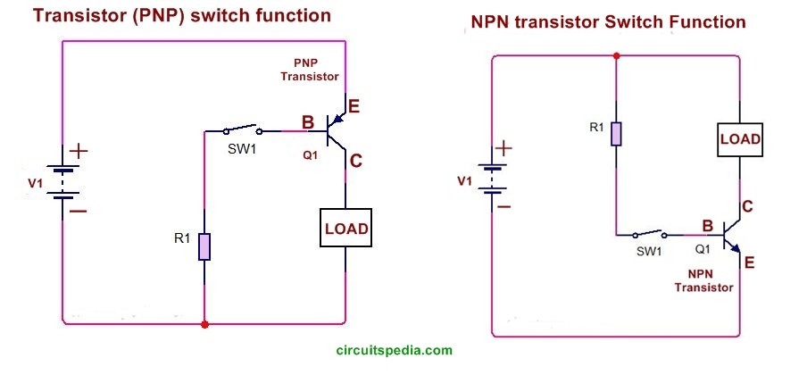
Mainly transistors are used for the switching purpose. another use of a transistor is as amplifier.
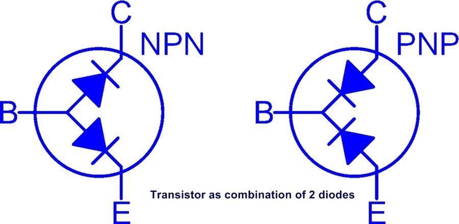
Transistor is made by using of 2 pn junction diode.
NPN= negative -positive-negative.
NPN transistor has both side material is n-type and between of both a positive (Hole) type material. Electrons are the majority carriers and holes are minority carriers.
The base of the NPN transistor is P-type and the Emitter is N-type and should be connected with the negative supply.
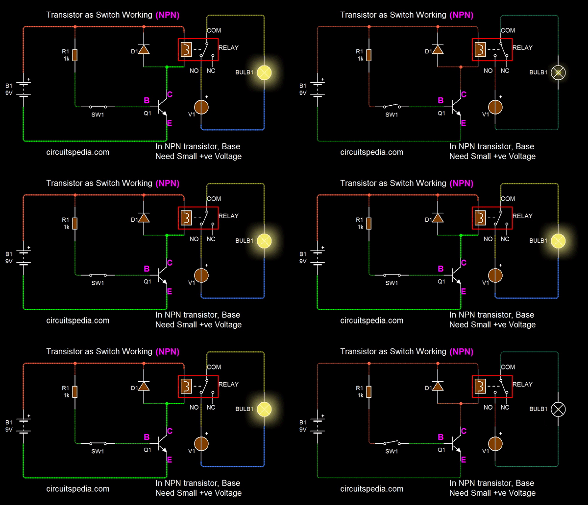
A small Positive current required at the Base terminal for turning on the transistor. By sending varying levels of current to the base, the amount of current flowing through the collector to the emitter may be regulated.
When we apply a small Positive supply at the base, then the Current between the emitter and collector will be passed and we say that the transistor is turned on. A very small amount of current may be used to control a large amount of current, this property is known as the amplifier.
The base of the transistor is used to switch current through the collector and emitter. When the base is between 0V and 0.7V it is switched off and when above 0.7V it is switched on and allowing the current to flow from the collector to the emitter.
In PNP type transistor we need a Negative voltage at the base terminal for turning on the transistor. In case of pnp the only difference is due to the p-type emitter and n-type base, holes are the majority carriers and electrons are minority carriers.
When we apply a small negative supply at the base of PNP then the current between collector and emitter will conduct.
PNP= Positive-negative-Positive
The following Animation shows the basic switching function using Relay for high current switching. If You need small current switching then without a relay, Directly you can connect the load with Collector .
Note – If use Relay in any circuit then a Diode (called as flyback diode) must connect with parallel of Relay input, This is essential for protection. Both with PNP and NPN transistor, Flyback diode is must in reverse bias.
The current supply between collector and emitter controlled by the supply signal of the Base terminal. If the signal at Base increase then also current conduction between emitter and collector increased. The base terminal of transistor works as the adjustable knob of any water tip/Bowl. That controls the amount of water passing through it.
The current conduction in a general transistor (NPN and PNP) is done by both polarities, negative supply as well as positive supply because of both minority and majority carrier. So this is called bipolar junction transistor (BJT).
Bipolar Junction Transistors operate within three different regions
- Active Region – the transistor operates as an amplifier
- Saturation – the transistor is “Fully-ON” operating as a switch and
- Cut-off – the transistor is “Fully-OFF” operating as a switch
BJT IS CURRENT CONTROLLED
A BJT is a current controlled device because its output characteristics are determined by the input current.
if the output variations are due to input current variations, then this device is current controlled and if the output variations are due to input voltage variations, then the device is voltage controlled.
BJT is a current controlled device but MOSFET is a voltage controlled device.
In Electronics Transistor is widely used for the switching purpose.
In Logic gate designing in digital circuits transistors are also used.
Also read
How To Make A Blinking LED Circuit With 555
Light Activated Switch using Transistor
Automatic Night Lamp Using LDR
Delay ON Timer circuit using transistor


Transistors are at the very core of today’s electronics technology. The development of the transistor has resulted in many changes to the world.
The introduction of the transistor has enabled many technologies we take for granted today: everything from portable transistor radios, through to cellular phones, and computers, remote operation, the functionality we take for granted in current day automobiles, etc . . . . All these and many more everyday items have all been made possible by the invention of the transistor.
What’s up, every time i used to check blog posts here in the early hours in the break of day, because i enjoy to learn more and more.
Wow, wonderful blog layout! How long have you been blogging for?
you make blogging look easy. The overall look of your site is magnificent, as
well as the content!
Keep this going please, great job!