LDR darkness sensor circuit
Contents
dark sensor circuit
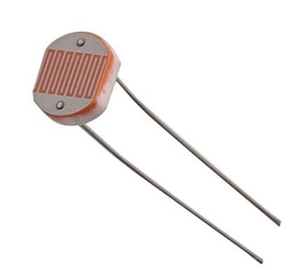
This Automatic light-operated light switch circuit is Based on LDR. LDR is a Light Dependent Resistor. It is also called a Photoresistor.
Introduction of LDR
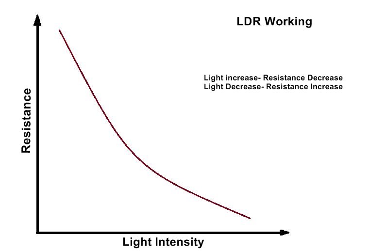
LDR (Photoresistor) is a type of variable resistor that Increases its Resistance when the Light is Decreases and its Resistance Decreases When Light is Increases. It means in a dark place or when no light falls on LDR, the resistance of its is very HIGH, and in Sufficient light, the resistance of LDR is very LOW.
The LDR (Light Dependent Resistor), also known as a photoresistor, is a type of resistor that changes its resistance based on the intensity of light falling on it. The working principle of an LDR involves the interaction between light and the semiconductor material within the resistor.
Working mechanism and Working principle of LDR
- Semiconductor Material: LDRs are typically made of semiconductor material, such as cadmium sulfide (CdS) or lead sulfide (PbS). This material exhibits photoconductivity, meaning its electrical conductivity varies with the light.
- Resistance and Illumination: In the absence of light or in low light conditions, the semiconductor material in the LDR has a high resistance, limiting the flow of electric current. As the intensity of light increases, the resistance of the LDR decreases, allowing more current to pass through.
- Energy Bands: The behavior of the LDR is explained by its energy band structure. In the dark or low light, the valence band of the semiconductor material is full, and the conduction band is empty, creating a wide bandgap. This wide bandgap results in a high resistance.
- Electron Excitation: When light photons strike the semiconductor material, they provide energy to the atoms in the material. This energy allows electrons in the valence band to jump to the conduction band, leaving behind holes in the valence band. This process is called electron excitation.
- Conductivity and Resistance: The excitation of electrons increases the number of charge carriers (electrons and holes) in the semiconductor material. This increased number of charge carriers reduces the resistance of the material, as they can carry electric current more easily.
- Light Intensity and Resistance: The intensity of light determines the number of photons striking the LDR and the extent of electron excitation. Higher light intensity leads to more electron excitation, resulting in a lower resistance of the LDR.
Applications of LDRs
- Automatic lighting systems: LDRs can detect ambient light levels and automatically switch lights on or off accordingly.
- Camera exposure control: LDRs are used in cameras to measure light levels and adjust exposure settings.
- Solar panels: LDRs are used to monitor light levels in solar panels to optimize their efficiency.
- Burglar alarms: LDRs can be used as part of security systems to detect changes in light levels that may indicate an intruder.
Remember that LDRs have their own specific characteristics and limitations, so it’s important to consult the datasheet or technical specifications of a particular LDR model to understand its operating range, sensitivity, and other relevant parameters.
This resistor works on the principle of photoconductivity. These devices depend on light. The most obvious application for an LDR is to automatically turn on a light at a certain light level.
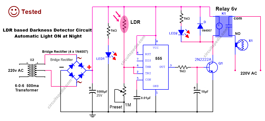
LDR circuit diagram
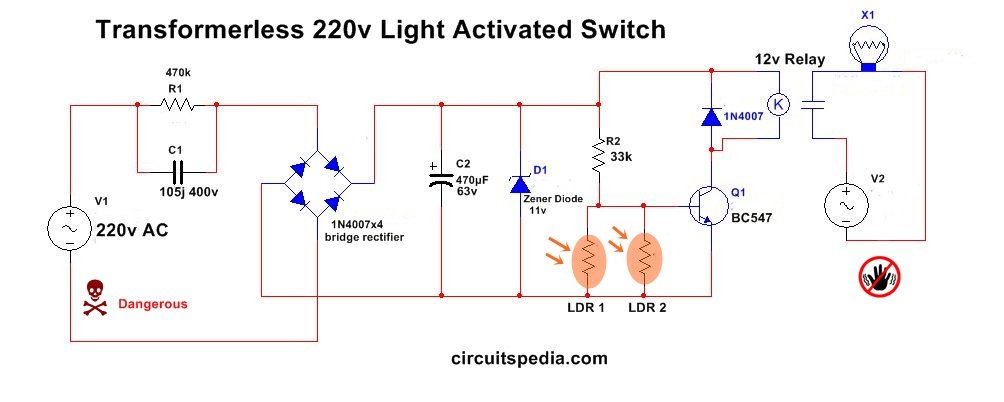
Circuit 1.
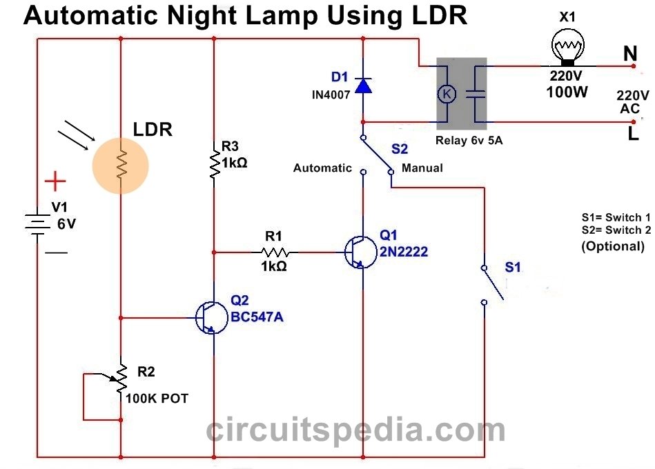
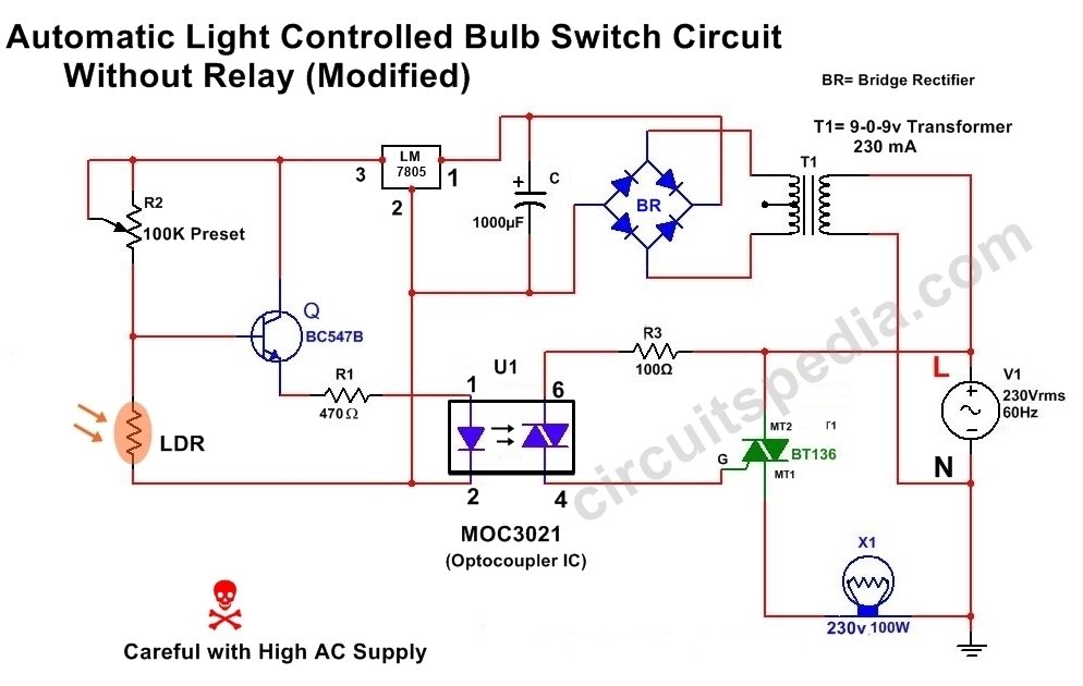
Circuit 2.
Construction And Working Of Circuit 2.
Construct the circuit as shown in Fig. Two NPN transistors are used to switch operations. The LDR is connected between the supply voltage and the Base terminal of transistor Q2. The Emitter terminal of this transistor is connected to the ground through a variable resistor or potentiometer (POT). This variable resistor is used to adjust the sensitivity of the circuit.
At Day When Light falls on LDR then conductivity increases and current flows between supply to the base of the transistor and then transistor Q1 will on. Transistor Q1 And Transistor Q2 are connected as NOT Gate. When transistor Q1 is on by conducting an even small current on base, The output of transistor Q2 is LOW (OFF).
At night when there is no light falls on LDR, then high resistance will create and there are no current flows on the base of transistor Q2. As there is no supply comes on the base of transistor Q1, this is in an OFF state, When this transistor has LOW input then the output of Transistor Q2 will be HIGH When transistor Q2 is in HIGH mode then is energized (turned on) the relay connected with its collector and Electric Lamp will be Switched ON.
Assemble the circuit at any general PCB board and set the adjustment of the pot according to the required sensitivity. Fix the LDR out of the cabinet for detecting the light.
components
LDR (medium size)-1
Transistor
BC547-1
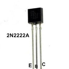
2N2222-1
Resistor
1K-2
POT or PESET–
100k-1
Relay 6v -1
Diode
1N4007-1
Also read
- What is DIAC
- FAN regulator Dimmer circuit (AC and DC)
- Difference between 12-0-12 and 0-12 transformer
- Remote controlled switch




tanks.i need a circuit as up with a capacitor about 1000 as timer .please help me.