Over-voltage Protection circuit using TL431 Shunt Regulator IC
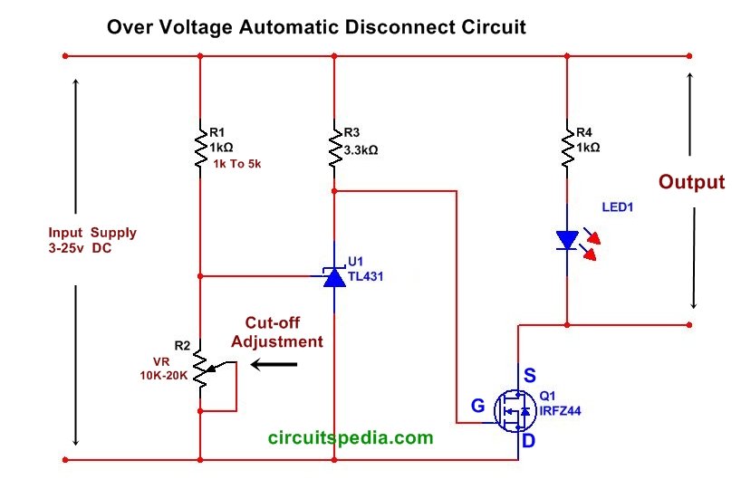
This circuit protects from high voltage. Automatic Equipment disconnect when the power cross the level of a fixed voltage. This is a safety device to overvoltage.
What is TL431
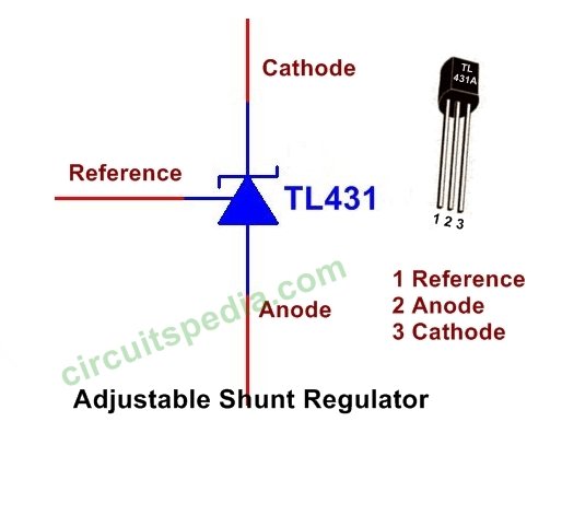
The TL431 is a three-terminal adjustable precision shunt regulator integrated circuit (IC). It is commonly used in electronic circuits as a voltage reference or precision voltage regulator. The TL431 provides a stable reference voltage that can be adjusted to a desired value using external resistors.
The TL431 operates by comparing the reference voltage at its reference terminal (typically 2.5V) with the voltage at its control terminal. Based on this comparison, it adjusts its internal resistance to maintain a constant voltage between the reference and control terminals. This makes it a versatile component for regulating voltage in various applications.
The control terminal of the TL431 is connected to an external voltage divider network consisting of resistors. By adjusting the values of these resistors, the output voltage of the TL431 can be set to a desired level. This makes it suitable for applications such as voltage regulation, voltage monitoring, overvoltage protection, and precision measurement circuits.
One of the key features of the TL431 is its high accuracy and low-temperature coefficient. It has a typical accuracy of ±1% and a low-temperature coefficient of around 50 ppm/°C, which means that it can provide a stable reference voltage even over a wide range of temperatures.
In addition, the TL431 has a low dynamic impedance, which means it can provide a relatively constant output voltage even when the load changes. It also has a wide operating voltage range and can handle currents up to a few milliamperes.
Overall, the TL431 is a popular choice for voltage regulation and precision reference applications due to its adjustable output, high accuracy, low-temperature coefficient, and ease of use.
As per the datasheet, TL431A is a three-terminal programmable integrated circuit. This is a shunt regulator diode. Look like a transistor. This monolithic IC voltage references operate as a low-temperature coefficient zener, which is programmable from Vref to 36 V with two external resistors. This device exhibits a wide operating current range of 1.0 mA to 100 mA with a typical dynamic impedance of 0.22 W. The characteristic references make it an excellent replacement for Zener diodes in many applications such as digital voltmeters, power supplies, and op-amp circuitry. The 2.5 V reference makes it convenient to obtain a stable reference from 5.0 V logic supplies, and since the TL431, A, B operates as a shunt regulator, it can be used as either a positive or negative voltage reference. Active output circuitry provides a very sharp turn-on.

• Typical Temperature Drift (TL431B) characteristic,
|
|
|
|
|
|
|
|
Advantages and disadvantages of the TL431
Advantages
- Adjustable Output: The TL431 allows for precise voltage regulation as it can be adjusted to a desired output voltage using external resistors.
- High Accuracy: The TL431 provides a high level of accuracy with a typical tolerance of ±1%. This makes it suitable for applications that require precise voltage references or regulation.
- Low-Temperature Coefficient: The TL431 has a low-temperature coefficient, typically around 50 ppm/°C. This means that the reference voltage remains relatively stable over a wide temperature range, enhancing its performance in temperature-sensitive applications.
- Wide Operating Voltage Range: The TL431 can operate over a wide voltage range, typically from 2.5V up to 36V. This flexibility allows it to be used in various circuits with different voltage requirements.
- Low Dynamic Impedance: The TL431 exhibits a low dynamic impedance, which means it can maintain a relatively constant output voltage even when the load current changes. This characteristic is beneficial in applications where a stable voltage source is required despite varying loads.
Disadvantages
- Current Limitation: The TL431 is limited in terms of the maximum current it can handle. While it can typically handle a few milliamperes of current, it may not be suitable for high-power applications that require larger current capabilities.
- Limited Output Voltage Range: Although the TL431 has a wide operating voltage range, the adjustable output voltage is limited by its reference voltage, typically 2.5V. This can be a disadvantage if the required output voltage falls outside this range.
- External Components: The TL431 requires external resistors to set the desired output voltage. The need for additional components increases the circuit complexity and footprint.
- Sensitivity to Input Noise: The TL431 can be sensitive to input noise and fluctuations. Proper filtering and decoupling techniques may be necessary to maintain stability and accuracy in noisy environments.
It’s important to consider these advantages and disadvantages when choosing the TL431 for a specific application, as they may impact its suitability and performance in different scenarios.
Also read
- Switch ON/Power ON and OFF Delay timer
- AC DC Fan regulator circuit/dimmer
- Dark sensor circuit
- Water level controller circuit
- Touch ON Touch OFF Switch circuit


Only wanna comment on few general things, The website layout is perfect, the content is real excellent. “The way you treat yourself sets the standard for others.” by Sonya Friedman.
Thanks man,
I was screwing around with Voltage monitors for the longest time. This is a much better solution to my problem.
PLEASE SIR I AM INTERESTED TO LEARN MORE FROM YOU, PLEASE I AM A FINAL YEAR STUDENT BUT AN ORPHAN WITH THIS PROJECT FROM MY DEPARTMENT THAT SEEM IMPOSSIBLE, BUT IMMEDIATLY I MEET YOU I KNOW IT WILL BE POSSIBLE BY GOD GRACE. THE PROJECT IS TO BUILD A POWER PACK SOLAR ENERGY THAT CAN POWER ALL HOUSE EQUIPMENT SUCH LIKE (CELINE FAN, TELEVISION, 5 DESKTOP COMPUTER’S, 10 LAPTOP’S, AC, AND FRIDGE. PLEASE I REALLY NEED YOUR HELP AND YOUR ASSISTANCE PLEASE SIR,
I WILL BE HAPPY TO HEAR FROM YOU SOON. GOD BLESS YOU AND YOUR FAMILY.
I have noticed in Solar heating of water with excess panel voltage there is a circuit similar but set up to switch the voltage on when the input reaches a set point . The opposite of overvoltage protection .
Mostly Input is about 65 volts from the panel and it is required to switch power to the water heater when the battery voltage gets to say 58 volts . The MPPT of the controller drops the voltage to what will charge the battery best ,usually about 56 volts so when it all comes up to 58 volts the current is diverted to the water . I have the basics of a circuit using an lm431 but I have not gotten it to work properly yet . Can you help?