High voltage Autocut Circuit For Stabilizer
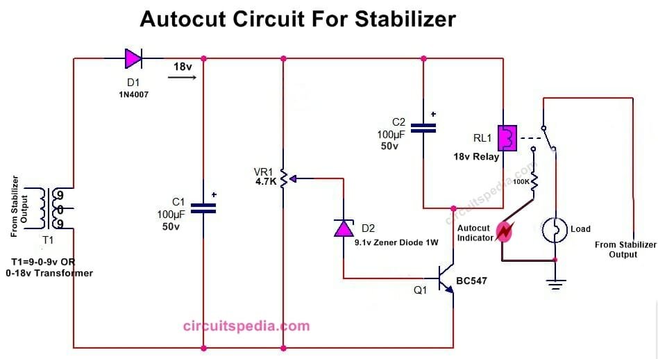
Auto cut voltage stabilizer circuit diagram
Here i am presenting a circuit of auto cut that is used mostly in manual voltage stabilizers. This is a protection circuit that protects electrical appliances from high voltage. This circuit is connected to the output of the stabilizer. When the voltage increase above the required set level then this circuit activates the relay and then the output is disconnected and not the risk of damage by the high voltage. A circuit is easy and simple.
Use either a 0-18v or 9-0-9v transformer of 500ma. Connect all components as a given diagram. In normal supply, the relay will deactivated mode, but when the voltage crosses a fixed voltage then the relay is automatically activated and the NO (normally open) pin of the relay will connect. Connect the Load with the NC pin of the relay.
After the full connection is completed Give the power supply and adjust the auto cut by moving the preset at which voltage level you want to set. Use Capacitors of minimum 50v value, it should not less than 50v because in the circuit high voltage supply flows. If you use a 12-0-12v transformer then use 24v relay.
circuit diagram 1
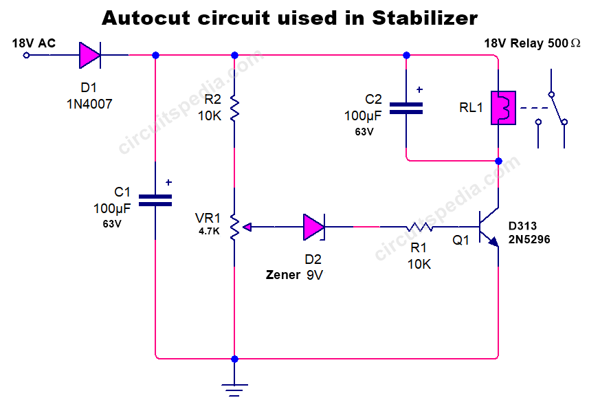
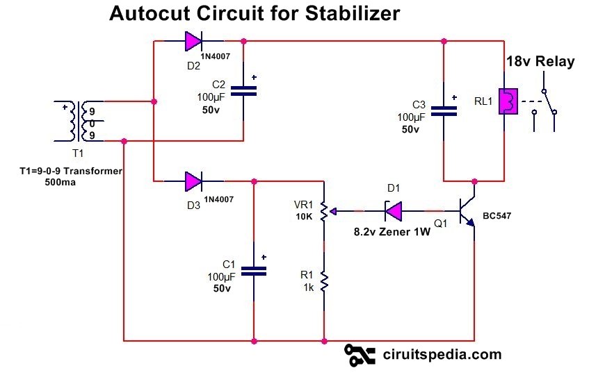
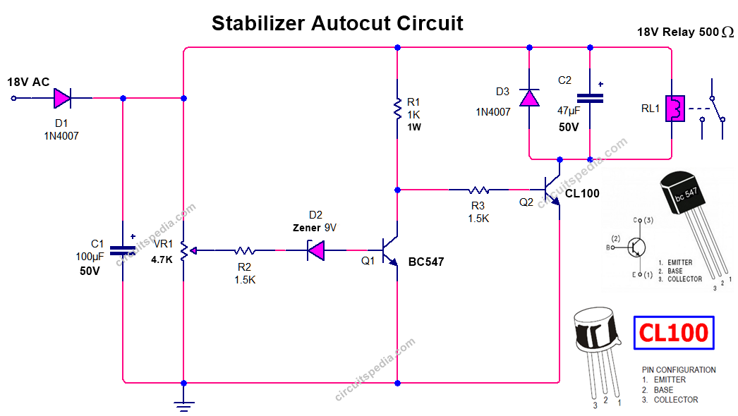
Here is another simple circuit of Autocut For manual stabilizer. In this circuit, there are small changes from the first circuit. if you use a 12-0-12 transformer then use a 24v relay. You can also check this circuit by connecting with a 0-12 transformer with a 12v relay. Use 500ma to 1 A Transformer.
circuit diagram 2
circuit diagram 3
Circuit diagram 4
Also read
- Automatic Stabilizer circuit diagram (2 Relay, 3 Relay)
- Overvoltage Autocutoff circuit using 741 opamp
- Switch ON/Power ON and OFF Delay timer
- AC DC Fan regulator circuit/dimmer
- Dark sensor circuit
- Water level controller circuit
- Touch ON Touch OFF Switch circuit

