Low Pass Filter Calculator
Low-Pass Filters: Your Guide to Understanding and Using Them
In the vast and fascinating world of electronics and signal processing, filters play an essential role. Think of them as electronic gatekeepers, selectively allowing certain parts of an electrical signal to pass through while blocking others. Just as a coffee filter lets liquid pass but holds back the grounds, an electronic filter allows specific frequencies to flow while attenuating or stopping others.
Among the most fundamental types of electronic filters is the low-pass filter. As the name suggests, a low-pass filter is designed to allow low-frequency signals to pass from its input to its output while significantly reducing or blocking high-frequency signals. These filters are ubiquitous, found in everything from simple audio equipment to complex communication systems and sensitive medical devices.
In simple words, a low-pass Filter is a circuit that allows only low-frequency signals to pass and blocks high-frequency signals.
Understanding how low-pass filters work, their different types, and their applications is a cornerstone of electronics knowledge. Whether you’re an electronics hobbyist, a student, or simply curious about the technology that shapes our world, this guide will provide a comprehensive and easy-to-understand overview of low-pass filters.
What Exactly is a Low-Pass Filter?
At its core, a low-pass filter is an electronic circuit that exhibits a specific frequency response characteristic: it passes frequencies below a certain point, known as the cutoff frequency (f_c), and attenuates frequencies above this point.
Imagine a signal as a mix of different frequencies, like a musical chord composed of various notes (each note having a different frequency). A low-pass filter acts like a sieve, letting the lower notes (low frequencies) pass through relatively unimpeded, while the higher notes (high frequencies) are significantly reduced in volume or blocked entirely.
The transition from “passing” to “blocking” isn’t usually abrupt. Instead, it typically occurs over a range of frequencies around the cutoff frequency. The steepness of this transition is determined by the filter’s order and design.
How Do Low-Pass Filters Work? The Basic Concept
Low-pass filters are typically built using fundamental electronic components like resistors (R), capacitors (C), and inductors (L). The way these components interact with signals at different frequencies is key to the filter’s operation.
- Resistors (R): Resistors oppose the flow of electrical current, and their resistance value is generally constant regardless of the signal frequency.
- Capacitors (C): Capacitors store electrical energy in an electric field. Their opposition to AC current, called capacitive reactance (X_C), decreases as the frequency increases. At very low frequencies (approaching DC), a capacitor acts like an open circuit, blocking current flow. At very high frequencies, it acts almost like a short circuit, allowing current to flow easily.
- Inductors (L): Inductors store electrical energy in a magnetic field. Their opposition to AC current, called inductive reactance (X_L), increases as the frequency increases. At very low frequencies (approaching DC), an inductor acts almost like a short circuit, allowing current to flow easily. At very high frequencies, it acts like an open circuit, blocking current flow.
By strategically combining these components, we can create circuits that offer less opposition to low frequencies and more opposition to high frequencies, thus filtering out the high-frequency components.
Simple Low-Pass Filter Circuits
The simplest low-pass filters are first-order filters, meaning they have one reactive component (either a capacitor or an inductor).
1. The RC Low-Pass Filter
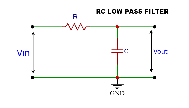
The RC low-pass filter is the most common and easiest to understand. It consists of a resistor (R) and a capacitor (C) connected in series with the input signal, with the output taken across the capacitor.
Circuit Diagram (RC Low-Pass Filter):
- The input voltage () is applied across the series combination of R and C.
- The output voltage () is measured across the capacitor (C).
- At Low Frequencies: The capacitive reactance $$X_c=\left(\frac1{2\mathrm{πfc}}\right)$$ is very high. The capacitor acts almost like an open circuit. Most of the input voltage appears across the capacitor, so the output voltage is nearly equal to the input voltage. Low frequencies pass through.
- At High Frequencies: The capacitive reactance () is very low. The capacitor acts almost like a short circuit. Most of the input voltage is dropped across the resistor (R), and very little voltage appears across the capacitor. The output voltage is much smaller than the input voltage. High frequencies are attenuated.
Cutoff Frequency (f_c) for an RC Low-Pass Filter:
The cutoff frequency is defined as the frequency at which the output voltage is 70.7% of the input voltage (or the power is half the input power). At this frequency, the capacitive reactance () is equal to the resistance (R).
$$R=X_c=\left(\frac1{2{\mathrm{πf}}_cC}\right)$$ Solving for :
Where:
- Is the cutoff frequency in Hertz (Hz)
- Is the resistance in Ohms ()
- Is the capacitance in Farads (F)
2. The RL Low-Pass Filter
An RL low-pass filter uses a resistor (R) and an inductor (L). In the low-pass configuration, the resistor and inductor are in series with the input, and the output is taken across the resistor.
Circuit Diagram (RL Low-Pass Filter):
- The input voltage () is applied across the series combination of L and R.
- The output voltage () is measured across the resistor (R).
How it Works:
- At Low Frequencies: The inductive reactance () is very low. The inductor acts almost like a short circuit. Most of the input voltage appears across the resistor, so the output voltage is nearly equal to the input voltage. Low frequencies pass through.
- At High Frequencies: The inductive reactance () is very high. The inductor acts almost like an open circuit. Most of the input voltage is dropped across the inductor (L), and very little voltage appears across the resistor. The output voltage is much smaller than the input voltage. High frequencies are attenuated.
Cutoff Frequency (f_c) for an RL Low-Pass Filter:
Similar to the RC filter, the cutoff frequency is where the inductive reactance () equals the resistance (R).
$$R=X_L=2{\mathrm{πf}}_{\mathrm c}\mathrm L$$
Solving for :
$$fc=\frac R{2\mathrm{πL}}$$
Where:
- is the cutoff frequency in Hertz (Hz)
- is the resistance in Ohms ()
- is the inductance in Henries (H)
While RL filters can function as low-pass filters, RC filters are generally more common in many applications due to the availability and smaller size of capacitors compared to inductors, especially at lower frequencies.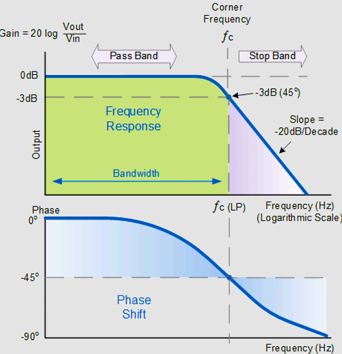
Understanding Frequency Response and Cutoff Frequency
The frequency response of a filter describes how the filter affects signals at different frequencies. For a low-pass filter, the ideal frequency response would be a perfect square wave: passing all frequencies below with no attenuation and completely blocking all frequencies above .
In reality, filters have a gradual transition. The cutoff frequency () is a standard reference point. It’s also known as the -3 dB frequency. Decibels (dB) are a logarithmic unit used to express ratios, often power or voltage ratios. A -3 dB point corresponds to an output power that is half the input power, or an output voltage that is times the input voltage.
The range of frequencies that a filter allows to pass is called the passband. For a low-pass filter, the passband is typically considered to be the frequencies from DC (0 Hz) up to the cutoff frequency (). The range of frequencies that are significantly attenuated is called the stopband. The region around the cutoff frequency where the transition occurs is called the transition band.
Bode Plots:
Frequency response is often visualized using Bode plots. A Bode plot typically consists of two graphs:
- Magnitude Plot: Shows the gain (output voltage/input voltage ratio, often in dB) versus frequency (on a logarithmic scale). For a low-pass filter, this plot shows high gain in the passband and decreasing gain in the stopband.
- Phase Plot: Shows the phase shift (the difference in timing between the output signal and the input signal) versus frequency. Filters introduce phase shifts, which vary with frequency.
For a simple first-order RC or RL low-pass filter, the magnitude plot rolls off at a rate of -20 dB per decade (or -6 dB per octave) above the cutoff frequency.
Types of Low-Pass Filters
Low-pass filters can be categorized in several ways:
1. Passive Filters
- Passive Low-Pass Filters: These filters are constructed using only passive components like resistors (R), capacitors (C), and inductors (L). The RC and RL filters discussed above are examples of passive filters. They are simple, inexpensive, and don’t require external power. However, they can introduce signal loss (attenuation) even in the passband, and their performance can be affected by the load connected to the output. They also cannot provide voltage gain.
-
Advantages of Passive Low-Pass Filters:
- Simple: They are easy to design and build using basic components.
- Inexpensive: Resistors, capacitors, and inductors are generally low-cost components.
- No External Power Required: They do not need a power supply to operate.
Disadvantages of Passive Low-Pass Filters:
- Signal Loss (Attenuation): They can reduce the signal strength even in the passband.
- Loading Effects: Their performance can be affected by the impedance of the circuit connected to their output.
- Cannot Provide Voltage Gain: They can only attenuate or pass the signal, not amplify it.
- Performance Limitations: Compared to active filters of the same order, they may have a less steep roll-off in the transition band.
2. Active Filters
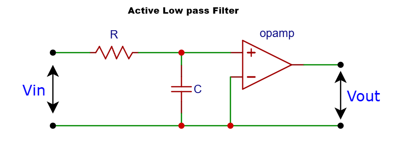
- Active Low-Pass Filters: These filters incorporate active components, most commonly operational amplifiers (op-amps), in addition to resistors and capacitors. Inductors are often avoided in active filters because they can be large, heavy, and expensive, especially at lower frequencies. Active filters require an external power supply to operate the active components.
- Advantages of Active Filters:
- It can provide voltage gain in the passband.
- Offer better performance (steeper roll-off, closer to ideal response) compared to passive filters of the same order.
- The input impedance is typically high, and the output impedance is low, making them less susceptible to loading effects.
- Easier to design for higher orders.
Disadvantages of Active Filters:
- Require a power supply.
- Can introduce noise and distortion due to the active components.
- Have a limited frequency range of operation determined by the active components.
-
Filter Design Types
Beyond the basic first-order RC or RL, low-pass filters can be designed using different mathematical approximations to achieve specific characteristics in their frequency response. Some common filter design types include:
- Butterworth Filter: Known for having the flattest possible frequency response in the passband. The transition band is smooth, and there is no ripple in the passband or stopband. Butterworth filters are often chosen when preserving the amplitude of signals in the passband is critical. The roll-off rate in the stopband is -20 dB per decade per order of the filter.
- Chebyshev Filter: Offers a steeper roll-off in the transition band compared to a Butterworth filter of the same order. However, this comes at the cost of ripple in either the passband (Type I Chebyshev) or the stopband (Type II Chebyshev). Chebyshev filters are useful when a sharper transition is needed, and some ripple is acceptable.
- Bessel Filter: Provides the flattest possible phase response in the passband, meaning it introduces minimal distortion to the shape of the signal (linear phase). This is particularly important in applications where preserving the timing relationships between different frequency components is crucial, such as in digital communication systems. The trade-off is a less steep roll-off in the transition band compared to Butterworth or Chebyshev filters of the same order.
- Elliptic Filter (or Cauer Filter): Offers the steepest roll-off in the transition band for a given order. This is achieved by allowing ripple in both the passband and the stopband. Elliptic filters are used when a very sharp cutoff is required, and ripple can be tolerated.
The choice of filter design depends on the specific application requirements, balancing the need for a flat passband, steep roll-off, and linear phase.
Higher-Order Low-Pass Filters
The order of a filter is determined by the number of reactive components (capacitors and inductors) it contains. A first-order filter has one reactive component, a second-order filter has two, and so on.
Increasing the order of a low-pass filter results in a steeper roll-off in the transition band. This means the filter transitions more sharply from passing frequencies to attenuating them.
Higher-order filters can be designed directly or by cascading (connecting in series) multiple lower-order filter stages. For example, cascading two first-order RC low-pass filters can create a second-order low-pass filter with a roll-off rate of -40 dB per decade.
Circuit Diagram (Second-Order RC Low-Pass Filter – Cascaded):
- This is a simple example of cascading two first-order RC stages. The cutoff frequency and overall response of the combined filter are influenced by the values of R1, C1, R2, and C2, and the interaction between the stages. For a true Butterworth, Chebyshev, etc., response, specific component values and possibly isolation stages (like op-amps) are needed.
Active filters make it much easier to design and implement higher-order filters with precise characteristics because op-amps can provide isolation between stages and contribute to the filtering action.
Applications of Low-Pass Filters
Low-pass filters are incredibly versatile and are used in a wide range of electronic applications:
Audio Systems:
-
- Tone Controls: Simple low-pass filters are used in treble cut controls to reduce high frequencies and make the sound warmer.
- Subwoofer Crossovers: Low-pass filters are essential in audio systems to direct only the low-frequency signals to the subwoofer speaker.
- Noise Reduction: Low-pass filters can help reduce high-frequency hiss or noise in audio recordings or playback.
Signal Processing:
-
- Smoothing and Averaging: Low-pass filters can remove rapid fluctuations or noise from a signal, providing a smoother representation.
- Anti-Aliasing: In analog-to-digital conversion (ADC), a low-pass filter is used before the ADC to remove frequencies higher than half the sampling rate (the Nyquist frequency). This prevents aliasing, which is when high frequencies are incorrectly represented as lower frequencies in the digital signal.
- Data Acquisition: Filtering out unwanted high-frequency noise from sensors before processing.
Power Supplies:
-
- Smoothing Rectified AC: After converting AC voltage to pulsating DC using a rectifier, a low-pass filter (often a capacitor alone or an LC filter) is used to smooth out the ripples and produce a more stable DC voltage.
Communication Systems:
-
- Receivers: Low-pass filters are used in radio receivers to select the desired low-frequency audio signal after demodulation and remove higher-frequency carrier signals and noise.
- Transmitters: Used to shape the transmitted signal and remove unwanted high-frequency components.
Control Systems:
-
- Feedback Loops: Low-pass filters can be used in control systems to filter out high-frequency noise in feedback signals, improving stability.
Medical Devices:
-
- ECG and EEG Machines: Low-pass filters are used to remove high-frequency noise and artifacts from sensitive biological signals like electrocardiograms (ECG) and electroencephalograms (EEG).
- Data Filtering: In various data analysis tasks, low-pass filters can be applied to time-series data to highlight trends by removing high-frequency variations.
Designing a Low-Pass Filter
Designing a low-pass filter involves determining the appropriate filter type (passive/active, Butterworth, Chebyshev, etc.), the order of the filter, and the component values (R, C, L, op-amp configurations) to achieve the desired cutoff frequency and frequency response characteristics.
For simple first-order RC or RL filters, the formulas for cutoff frequency are straightforward. For higher-order or more complex filter designs, specialized filter design software or online calculators are often used to determine the component values based on the desired specifications.
Example Design (First-Order RC Low-Pass Filter):
Let’s say you want to design a simple RC low-pass filter with a cutoff frequency of 1 kHz.
We know the formula: $$fc=\frac1{2\mathrm{πRC}}$$
We need to choose values for R and C. Let’s choose a common capacitor value, say ( F).
Now, we can solve for R:
$$R=\frac1{2{\mathrm{πf}}_{\mathrm c}\mathrm C}$$
$$R=\frac1{2\mathrm\pi\times100\mathrm{HZ}\times0.1\times10^{-6}\mathrm F}$$
$$R=\frac1{2\mathrm\pi\times10^{-4}\mathrm F}$$
$$R\approx\frac1{0.0006283}$$
$$R\approx1591.5$$
So, a resistor of approximately and a capacitor of would give you a first-order RC low-pass filter with a cutoff frequency around 1 kHz. In practice, you would use the nearest standard resistor value.
Conclusion
Low-pass filters are fundamental building blocks in electronics, essential for shaping signals and removing unwanted high-frequency components. From simple RC and RL circuits to complex active filters with specialized response characteristics, understanding how these filters work and where they are used is crucial for anyone involved in electronics or signal processing.
By controlling which frequencies are allowed to pass, low-pass filters enable us to clean up noisy signals, separate different frequency bands, smooth out variations, and ensure that electronic systems operate safely and effectively. The formulas governing their behavior, particularly the cutoff frequency, provide the tools needed to design and analyze these essential circuits.
Whether you’re filtering audio for a crystal-clear sound, processing data for accurate analysis, or ensuring the stability of a control system, low-pass filters are silently working behind the scenes, making modern electronics possible.
Keywords: low pass filter, RC filter, RL filter, active filter, passive filter, cutoff frequency, frequency response, filter design, signal filtering, audio filter, anti-aliasing filter, electronic filter, circuit diagrams, filter formulas.
More Tutorials and Tools
-
Watt to ampere converter | Power to current conversion
-
capacitor Code-to-value and value-to-code converter
-
Audio Amplifier circuit
-
DC Dimmer circuit using PWM
-
Switch on delay timer circuit

