How to make darkness circuit (4 circuits)
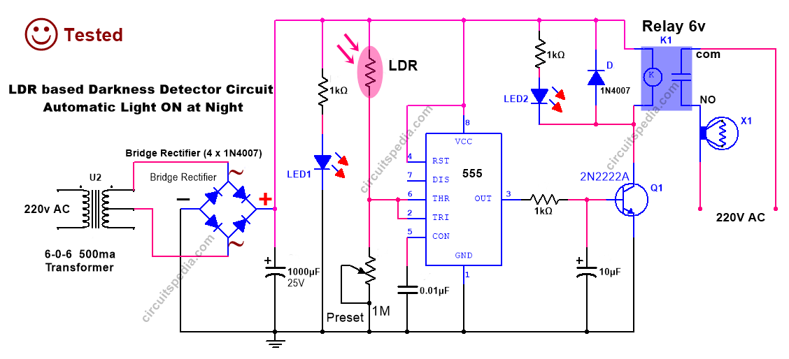
Circuit 1. LDR Darkness circuit diagram using 555
1. Introduction to LDR-Based Darkness Detectors
An LDR (Light Dependent Resistor)-based darkness detector circuit is a simple yet highly useful electronic system that automatically turns on a load (often a light bulb) when ambient light falls below a certain threshold. This type of circuit is widely employed in:
- Streetlights that turn on at dusk and off at dawn
- Night lamps in hallways or gardens
- Security lighting systems
The circuit typically uses an LDR as the sensing element, a comparator or operational amplifier (in this case, a 555 timer IC in a comparator-like setup), and a relay to switch higher voltage loads on and off.
2. Key Components in the Circuit
Before we delve into the specific schematic, let’s outline the primary components:
LDR (Light Dependent Resistor):
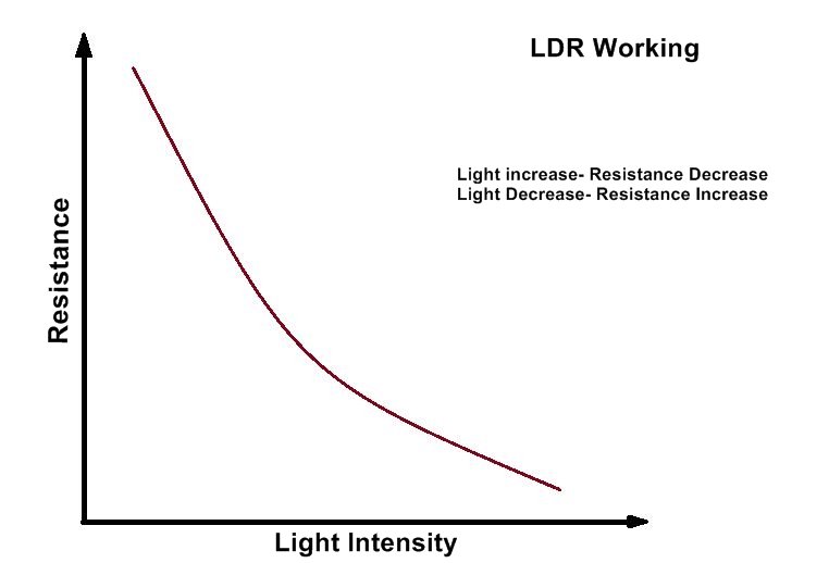
- Varies its resistance with light intensity.
- Higher resistance in low light, lower resistance in bright light.
Resistors and Potentiometer:
- Fixed resistors (e.g., 1 kΩ) to set current limits.
- A preset (potentiometer) for adjusting the sensitivity threshold.
555 Timer IC:
- Configured in a way that compares the voltage from the LDR’s divider to a reference.
- Outputs a signal to drive the relay circuit.
Transistor (e.g., 2N2222):
- Amplifies the 555’s output signal.
- Drives the relay coil with sufficient current.
Diode:
- Bridge Rectifier (4 × 1N4007): Converts AC from the transformer secondary to DC.
- Protection Diode (1N4007) across the relay coil to protect the transistor from back-EMF.
Relay (6V coil):
-
-
Acts as an electromechanical switch to control the AC load (e.g., 220V AC lamp).
-
Transformer (6-0-5, 500 mA):
-
-
Steps down the main AC voltage (220V) to a lower AC voltage suitable for the relay coil and the 555 IC power supply.
-
3. Circuit Diagram Overview
From the uploaded diagram, you’ll notice:
- AC Mains (220V) on the left, feeding a step-down transformer with a 6-0-6 secondary winding.
- A bridge rectifier made of four diodes (1N4007) provides DC output from the transformer’s secondary.
- A filter capacitor (not explicitly labeled in the diagram but usually present) smooths the DC.
- The 555 timer in the middle, connected to an LDR and resistors forming a voltage divider at its input (Trigger pin 2).
- The transistor (Q1, 2N2222) on the output side of the 555 drives the relay coil.
- The relay contacts switching the AC load (e.g., a bulb) connected to the 220V line.
4. Power Supply Section
Transformer:
- Takes 220V AC and steps it down to around 6V AC.
- The center-tapped or dual secondary (6-0-5) allows some flexibility in generating the required DC levels.
Bridge Rectifier:
- Four diodes (1N4007) are arranged in a full-wave rectification pattern.
- Converts the low-voltage AC to pulsating DC.
Smoothing/Filter Capacitor (often present though not always shown):
-
-
After rectification, a large electrolytic capacitor filters out the ripples, providing a more stable DC to the rest of the circuit.
-
5. LDR and 555 Timer Section
LDR and Resistor Network
- The LDR is connected in series or as part of a potential divider with a fixed resistor (1 kΩ) and/or a preset/potentiometer.
- As ambient light changes, the LDR’s resistance varies, altering the voltage at the 555’s Trigger (pin 2) or Threshold (pin 6) input (depending on the exact configuration).
555 Timer Configuration
- In many darkness detector circuits, the 555 is used in a comparator-like configuration.
- Pin 2 (Trigger): Monitors the voltage coming from the LDR divider.
- Pin 3 (Output): Goes high or low depending on whether the input signal at pin 2 crosses the set threshold.
- Pin 1 (Ground): Connected to the circuit ground.
- Pin 8 (VCC): Connected to the positive supply from the rectifier (and any filtering or regulation).
- Pin 4 (Reset): Usually tied to VCC to avoid resetting the IC inadvertently.
- Pin 7 (Discharge): In some designs, it might be tied into the resistor network or left unconnected if only comparator action is needed.
By adjusting the preset resistor in the voltage divider, you set the exact light level at which pin 2 triggers the 555 output.
6. Relay Driver and Output
Transistor Driver (Q1, 2N2222)
- The transistor receives the 555’s output signal from pin 3 through a current-limiting base resistor (often 1 kΩ).
- When pin 3 goes high, the transistor switches on, allowing current to flow through the relay coil.
Relay Coil and Contacts
- The relay coil is energized by the transistor, drawing current from the DC supply.
- Protection Diode (D2): A diode (1N4007) is placed across the relay coil to protect the transistor from back-EMF (a voltage spike generated when the coil is switched off).
- Relay Contacts (NO, NC, COM): The diagram shows a Normally Open (NO) contact used to control a 220V AC load. When the relay is energized (dark condition), the contact closes and powers the load (e.g., a lamp).
7. Step-by-Step Working Principle
Normal/Daylight Condition:
- The LDR has a low resistance in bright light.
- The voltage at pin 2 of the 555 remains below the trigger threshold (depending on the preset setting).
- As a result, pin 3 output stays low, the transistor is off, and the relay is not energized. The connected load remains off.
Decreasing Light/Dusk:
- As light intensity drops, the LDR’s resistance increases.
- This change shifts the voltage divider output at pin 2 of the 555, eventually reaching a level that triggers the IC.
Triggering the 555:
-
-
Once the voltage at pin 2 crosses the threshold (which you set with the potentiometer), the 555’s output (pin 3) goes high.
-
Relay Activation:
- A high output at pin 3 drives the transistor’s base.
- The transistor conducts, allowing current through the relay coil.
- The relay switches and connects the NO (Normally Open) contact to COM, powering the AC load (e.g., turning on a lamp).
Dark Condition:
- In complete darkness, the LDR’s resistance remains very high.
- The 555 continues to see the “dark” voltage level, keeping the output high and the relay energized.
Return to Light:
- When ambient light returns (morning or a bright source), the LDR resistance drops.
- The voltage at pin 2 shifts below the threshold, causing the 555’s output to go low.
- The transistor turns off, de-energizing the relay and turning the load off.
8. Adjusting Sensitivity
A preset potentiometer (often shown as “Preset” in the diagram) is included to fine-tune the trigger level. Here’s how you adjust it:
- Choose a Reference Light Condition: Decide on the light level at which you want the circuit to activate.
- Adjust the Potentiometer: Slowly turn the preset until the relay just toggles.
- Test and Recheck: Check the circuit’s response at slightly different light levels (e.g., early dusk, deeper darkness) to confirm proper operation.
This flexibility allows you to customize the circuit to your specific environment or application needs.
9. Practical Tips and Applications
Mounting the LDR:
-
-
Place the LDR where it can accurately sense ambient light changes. Avoid direct exposure to strong indoor lighting if you only want to detect external sunlight levels.
-
Shielding and Enclosures:
- If installing outdoors, protect the circuit from moisture and extreme temperatures.
- Use a transparent or translucent cover over the LDR to prevent water damage.
Power Rating and Safety:
- Ensure the transformer and relay can handle the current required by your load.
- Always use proper insulation and safety precautions when working with 220V AC.
Possible Modifications:
- Add an on-board LED to indicate when the relay is energized.
- Replace the mechanical relay with a solid-state relay (SSR) for quieter operation if desired.
Application Examples:
- Streetlights: Automatic switching on at night and off in daylight.
- Security Lighting: Illuminates dark areas to deter intruders.
- Indoor Night Lamps: For hallways, children’s rooms, or staircases.
10. Conclusion
This LDR-based Darkness Detector Circuit harnesses the changing resistance of an LDR under varying light conditions to toggle a 555 timer’s output. The 555 output then drives a transistor, which energizes a relay to switch on high-voltage loads. The entire setup is powered by a stepped-down AC supply, rectified and filtered to provide DC for the 555 and relay coil.
By carefully adjusting the potentiometer, you can fine-tune the exact light level at which the relay engages, making this circuit highly versatile for a wide range of automatic lighting applications. The combination of low-cost components and reliable operation ensures that this design remains a go-to solution for anyone needing an automatic night light or a darkness-activated switch.
Whether you’re an electronics hobbyist, a student, or a professional looking to implement automatic lighting solutions, this LDR-based system offers both simplicity and effectiveness. By understanding each section—power supply, sensing, control, and output— you can easily customize and troubleshoot the circuit to meet your specific requirements.
Components
capacitor
1000uf 25v -1
10uf 25v -1
0.01 uf -1
Resistor
1KΩ – 3
LDR – 1
Bridge Rectifier -1 or 1N 4007 diode – 4 pc for making Bridge rectifier
1N4007 diode – 1
IC 555 – 1
Transistor – 2N2222A- 1
Relay 6V – 1
Preset 1MΩ – 1
——————————-
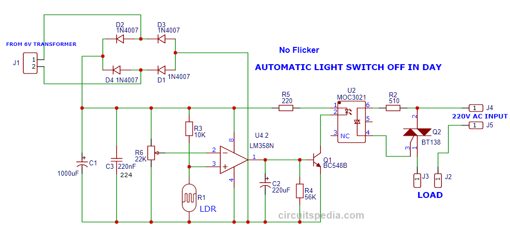
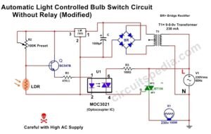
Circuit 2. LDR Darkness circuit using the comparator
√ Tested
Note- LDR must keep away from the light of the load bulb for flickerless operation. You can do this using the covering of the side area of LDR using black tape.
LDR and Resistor Network
- The LDR typically connects in a voltage divider with a fixed resistor (or potentiometer) to create a reference voltage that changes with light intensity.
- In bright light, the LDR’s resistance is low, pulling the voltage at the comparator’s input down.
- In darkness, the LDR’s resistance increases, raising the voltage at the comparator input.
Comparator Function (LM358/LM393)
- The op-amp or comparator monitors this varying voltage from the LDR divider on its inverting or non-inverting input (depending on design).
- The other input receives a stable reference voltage (often derived from a resistor divider connected to the supply).
- When the voltage at the LDR input crosses the reference threshold, the comparator’s output changes state.
Optocoupler and Triac Section (MOC3021 & BT138)
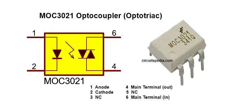
MOC3021 (Optocoupler)
- Inside the MOC3021, there is an LED that, when powered, activates an internal phototriac.
- This isolates the low-voltage control circuitry (comparator output) from the high-voltage AC line, providing safety and noise immunity.
- The comparator’s (or transistor’s) output drives the LED through a current-limiting resistor (e.g., R5).
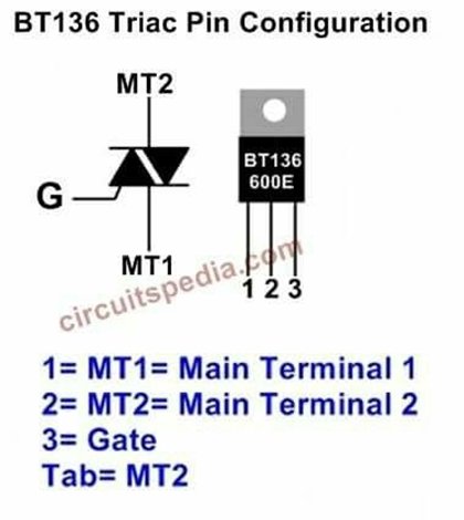
Triac (BT138)
- The BT138 triac switches the AC load.
- Once the phototriac in the MOC3021 conducts, it triggers the triac’s gate, allowing current to flow through the load.
- Because triacs conduct in both halves of the AC cycle, they are ideal for AC switching applications such as lamps or motors.
Daytime (Bright Light)
- The LDR has low resistance, causing the comparator’s input to remain below the reference threshold.
- The comparator’s output is low, meaning no current flows through the MOC3021 LED.
- The triac remains off, and the load (lamp) is off.
Dusk (Decreasing Light)
- As ambient light decreases, the LDR’s resistance rises.
- Eventually, the voltage at the comparator input surpasses the reference threshold.
- The comparator’s output goes high, sending current through the LED in the MOC3021.
Optocoupler Activation
- The MOC3021 LED activates the internal phototriac, which triggers the BT138 triac.
- The triac conducts AC power to the load.
Nighttime (Darkness)
- The LDR remains in high resistance mode, keeping the comparator’s output high.
- The load stays on throughout the night.
Return to Day
- When light levels rise again, the LDR resistance drops, pulling the comparator input below the threshold.
- The comparator output goes low, turning off the MOC3021 LED, and the triac stops conducting.
- The load is switched off, preventing daytime power consumption.
Circuit Construction and Connections
Transformer and Rectifier
- Connect the 6V AC secondary to the bridge rectifier (D1–D4).
- Output of the bridge goes to the filter capacitor (C1).
Comparator Section
- The LM358/LM393 power pins connect to the filtered DC supply.
- One comparator input (inverting or non-inverting) connects to the LDR divider.
- The other input connects to a reference voltage set by fixed resistors or a potentiometer.
Output to Optocoupler
- The comparator’s output pin goes to the optocoupler LED (inside MOC3021) via a resistor (R5).
- Ensure correct polarity: the LED inside the MOC3021 has an anode and cathode that must match the comparator output and ground.
Optocoupler to Triac
- The phototriac output pins of the MOC3021 connect to the gate of the BT138 triac and the AC line (through suitable connections).
- Refer to the MOC3021 datasheet to identify pin configuration.
Triac and Load
- The BT138 triac is in series with the load (e.g., a lamp).
- The load is then connected to the mains supply (220V AC or 110V AC) as indicated in the schematic.
- Use proper heat sinking if necessary for high-power loads.
Tips for Setting Up and Testing
Safety First
- You are dealing with mains voltage. Ensure all connections and insulating measures are properly done.
- Use a fuse or circuit breaker in series with the AC line for protection.
Initial Power-Up
- Test the low-voltage side (transformer, rectifier, comparator) before connecting the triac to the mains.
- Verify the comparator output toggles correctly with changes in light on the LDR.
Sensitivity Adjustment
-
-
Some designs include a potentiometer in series with the LDR. Adjust this pot to set the exact switching threshold for day/night transitions.
-
Enclosure
-
-
If using this outdoors, place the LDR in a transparent or translucent enclosure. Protect the rest of the circuit from moisture.
-
Practical Applications
- Outdoor Lighting: Streetlights, garden lamps, and security floodlights that turn off during the day.
- Indoor Automation: Night lights in corridors, staircases, or basements that only turn on when it’s dark.
- Energy Conservation: Ensuring lights don’t remain on unnecessarily, saving electricity costs.
- Commercial Signage: Billboards or signage that only need to be lit during dark hours.
11. Conclusion
This Automatic Light Switch OFF in Day circuit provides a robust, no-flicker solution by combining an LDR, a comparator (LM358/LM393), an optocoupler (MOC3021), and a triac (BT138). The comparator cleanly switches between on/off states based on ambient light, driving the optocoupler LED, which in turn triggers the triac. This design ensures stable, reliable operation even at borderline light levels, thanks to isolation from the AC line.
By following the outlined circuit construction, ensuring proper connections, and making use of best practices (like careful adjustment of the threshold and adequate safety precautions), you can create an efficient lighting control system. Whether you want to illuminate your porch, street, or indoor area only at night, this circuit helps you automate lighting in a hassle-free manner—saving energy and extending the life of your bulbs and other electrical equipment.
Demo testing Video Of LDR Darkness circuit using the comparator
Components
Resistors
10K-1
220Ω-1
510Ω or 470Ω -1
56K-1 (Not compulsory)
Capacitors
1000uf 25v-1
220 nf (224)-1
C2 = 220uf or 100uf 25v-1
Variable resistor 22K-1
Diode
1N4007-4
Transformer
0-6v 500ma- 1
IC
LM358 (comparator)-1
MOC3021 (optocoupler- 1
Transistor BC548-1
Triac BT138-1
LDR (12mm)-1
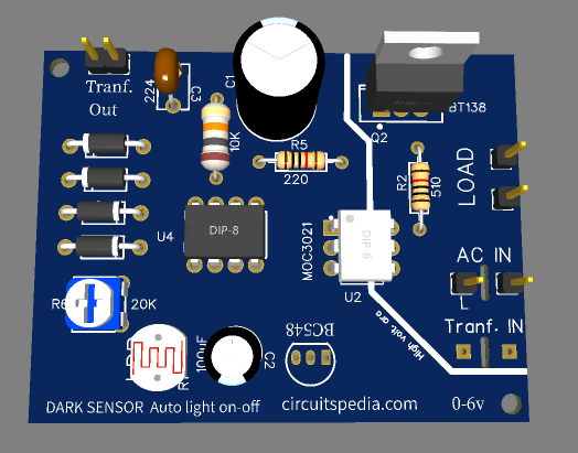
Download – Gerber_PCB_ldr
————————————-
Circuit 3&4.
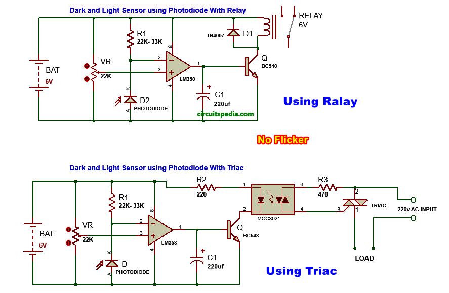
Photodiode darkness circuit diagram
This circuit diagram is made using the photodiode as the light sensor or dark sensor with the lm358 comparator. Highly sensitive and flickerless.
√ Tested
Video of photodiode dark sensor circuit
.
As my testing experience, Although Both LDR and Photodiode based circuit works well, But The LDR based circuit is better than photodiode based darkness circuit.
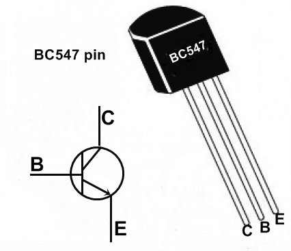
Note- Pinout of transistor BC547 and BC548 are same
Also Read
- Single Touch ON OFF Switch Using 555 And 4017
- 12v Battery Charger circuit with Overcharge Protection
- Stereo Audio Amplifier Circuit Using CD6283
- How To Connect A Microphone with Any Amplifier






Sir please giveme password Garber file
There is no password, just click on link to download the gerber file.
throught this circuit i think dc can not produce ac as matter of dc concerned.
What do you want to say, please clear
Wow I love this site,
But pls can I get any 3.7v, to 5vs, sound amplifier pls.