12v battery charge level indicator circuit led bar graph
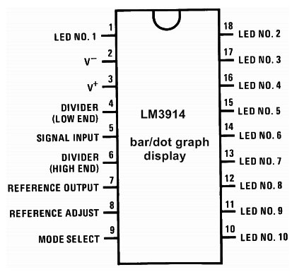
The LM3914 is a monolithic integrated circuit that senses analog voltage levels and drives 10 LEDs, providing a linear analog display. This ic is used for Dot and Bar Display. A single pin changes the display from a moving dot to a bar graph. The current drive to the LEDs is regulated and programmable, eliminating the need for resistors. This feature is one that allows operation of the whole system from less than 3V.

From datasheet – The linear scaling of the output thresholds makes the device usable, for example, as a voltmeter. In the basic configuration, it provides a ten-step scale that is expandable to over 100 segments with other LM3914 ICs in series.
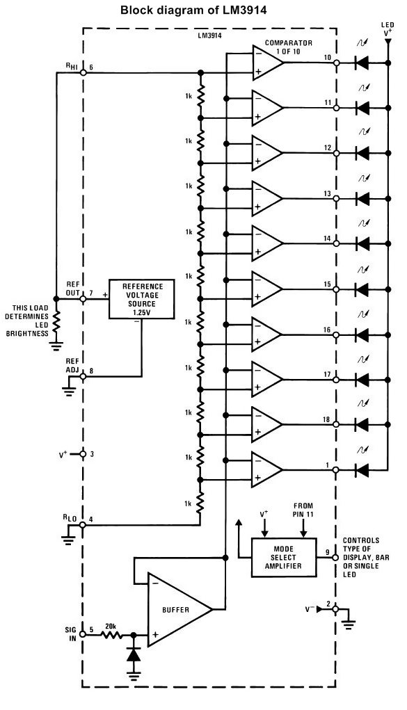
The simplified LM3914 block diagram is to gives a general idea of the circuit’s operation. A high input
impedance buffer operates with signals from ground to 12V and is protected against reverse and overvoltage
signals. The signal is then applied to a series of 10 comparators; each of which is biased to a different
comparison level by the resistor string.
The LM3914 is relatively low-powered itself, and since any number of LEDs can be powered from about 3V, it is
a very efficient display driver. The typical standby supply current (all LEDs OFF) is 1.6mA (2.5mA max). However,
any reference loading adds 4 times that current drain to the V+ (pin 3) supply input. For example, an LM3914
with a 1mA reference pin load (1.3k), would supply almost 10mA to every LED while drawing the only 10mA from its
V+ pin supply. At full-scale, the IC is typically drawing less than 10% of the current supplied to the display.
DOT OR BAR MODE SELECTION
The voltage at pin 9 is sensed by comparator C1, nominally referenced to (V+ − 100mV). The chip is in bar mode
when pin 9 is above this level; otherwise, it’s in dot mode. The comparator is designed so that pin 9 can be left
open-circuit for dot mode.
Taking into account comparator gain and variation in the 100mV reference level, pin 9 should be no more than
20mV below V+ for bar mode and more than 200mV below V+ (or open circuit) for dot mode. In most
applications, pin 9 is either open (dot mode) or tied to V+ (bar mode). In bar mode, pin 9 should be connected
directly to pin 3. Large currents drawn from the power supply (LED current, for example) should not share this
path so that large IR drops are avoided.
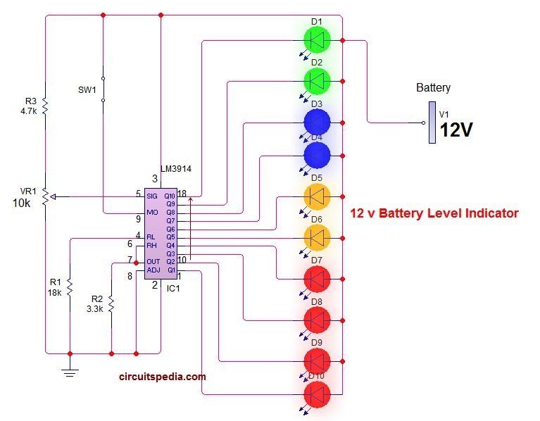
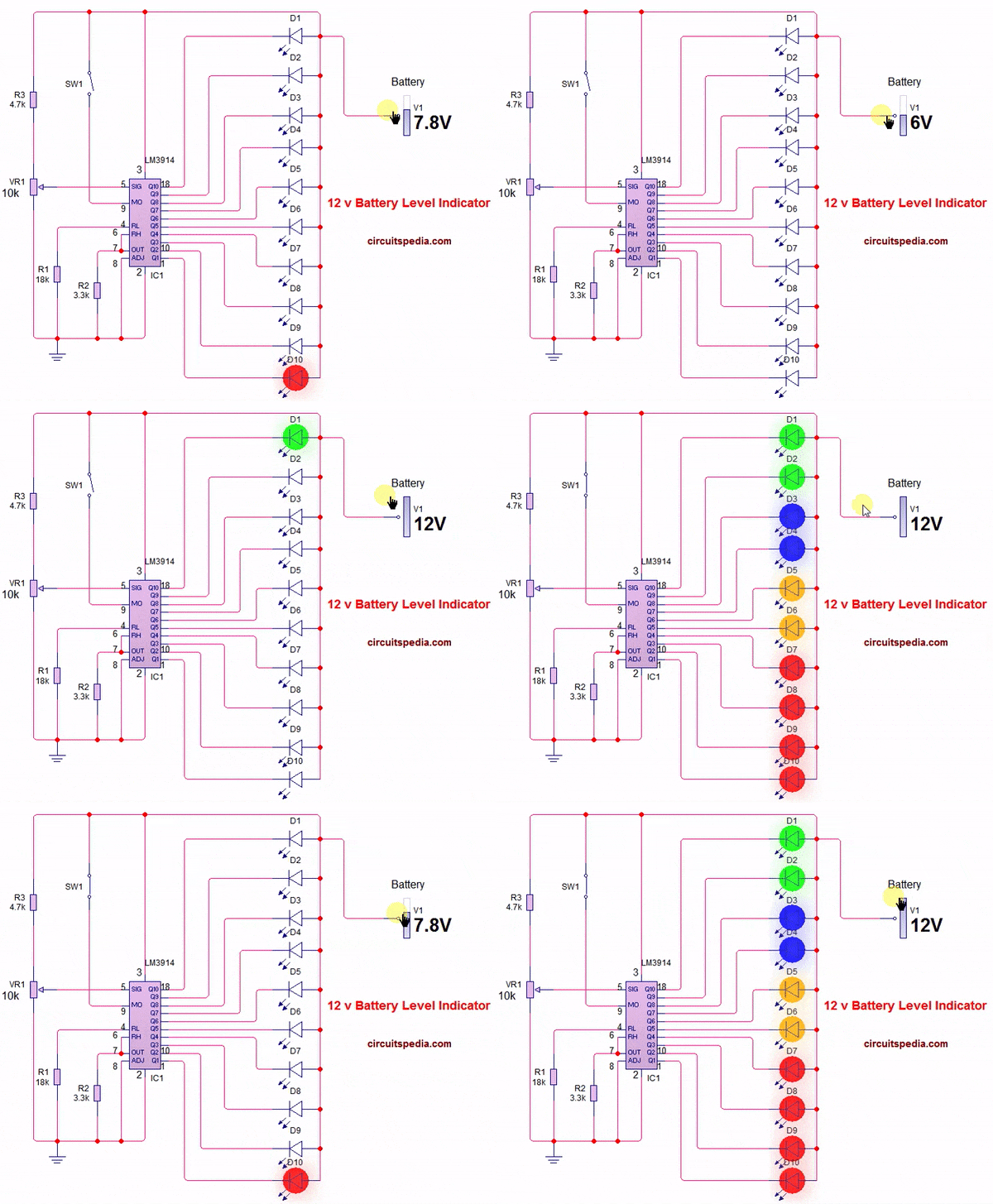
In Dot display mode only one led will glow and when Bar display is on then more than one led or all LEDs will glow as per voltage level sensed by ic. Adjust the variable resistor according to voltage sense and led display. when the switch s1 turns on then the Dot display changed into Bar display. Simply changed the Dot to Bar and Bar to Dot by the changing with switch on off connected with Mode terminal (pin 9)with positive. This circuit provides a beautiful visual indicator for the 12v battery voltage level.
Schematic diagram
Components
LM3914 ic-1
Resistor 18k-1, 3.3k-1, 4.7k-1
Preset 10k -1
LED -10 (Colour as per your choice)
switch-1





Спасибо за информацию!!!!!
This is a fantastic circuit design! The use of the 3914 IC for a 12V battery charge level indicator is a clever choice. I appreciate the detailed explanation and clear schematic provided. I’m excited to try this out in my next project. Thanks for sharing!
Great post! The use of the 3914 IC for a battery charge level indicator is really clever. I appreciate the detailed explanations and circuit diagrams. This will definitely help me in my upcoming projects. Thanks for sharing!