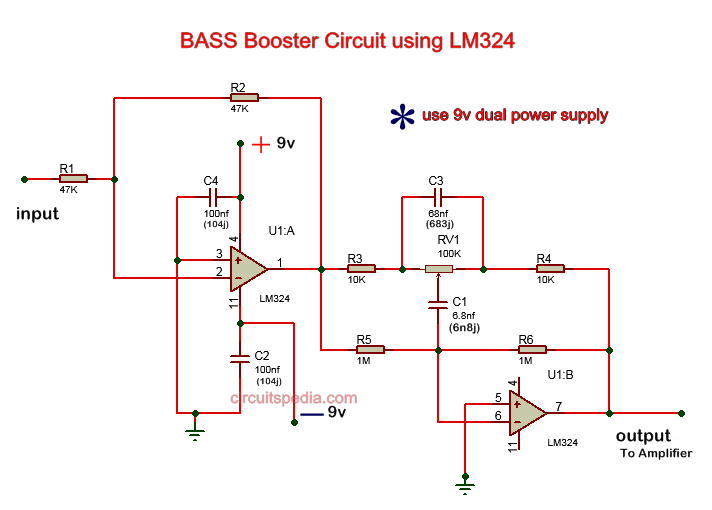
Bass booster circuit diagram
This bass booster circuit is made using the quad op-amp ic LM324. This op-amp ic has 4 operational amplifiers, but in this circuit, only 2 op-amps are used. This circuit provides Low pass filter of input audio which produces a Low frequency of input and high frequency is blocked.
Connect the circuit as the given diagram as below . Give input through the 47K resistor at pin no 2, one other 47 K resistor is connected between the pin 1 and pin 2. Pin 1 is the output pin of 1st opamp and this output pin is connected with 2nd op-amp input inverting pin 6 through resistors and capacitors. Pin no 4 is connected with +9v supply. pin 11 is connected with -9v and connect the ground with given terminals in diagram. Use dual power supply for the operation of this circuit.RV1 is 100k preset for adjusting the level of frequency. Pin no 7 is the output of 2nd opamp and this pin is used in this circuit as the output also. Output must be connected to the amplifier input.
Schematic diagram


