Tone Controller / BASS And TREBLE Controller
When you listen audio from any sound Producer Like Tv, Radio, CD/DVD Player, Home Theater Etc. You Notice that there are a controller to control the Effect of output sound as you want to Level Of Effect of Audio listen. This may not necessary to all audio Player has audio Effect controller (Tone Controller).
Tone controller provides Enhanced sound quality At Desisred Shape Of Equalizing Frequancy with respect to direct Monochrome Sound . Each Listener have different Sound Choices And According To their choices They can Control By Simply Adjustment Of Variable resistor (POT).
Tone Control is basically An Equalizer That Maintain The Audio Output Effect at Maximum Required Frequency Shape As Listener Choice.
If you want to add a effect tone controller. Which make that audio more sensible and effective clear, then you can make itself by using some components.
Tone Controller May include bass and the treble controls. The bass control is nothing but a low pass electronic circuit which filters and allows only the specified low frequency signals to pass into the amplifier stage and blocks other irrelevant frequencies.
When Increases The BASS Level at higher then it produces sound outputs which are “heavier” in response.
The Treble control produces just the opposite effects. At higher levels the treble circuit will sweep out all signals which are below the specified frequency range and Get only the high pitched sounds. With this control at max, the inputs consisting of sharp sound contents like chirping of birds, guitars, violins become predominant at the amplifier output.
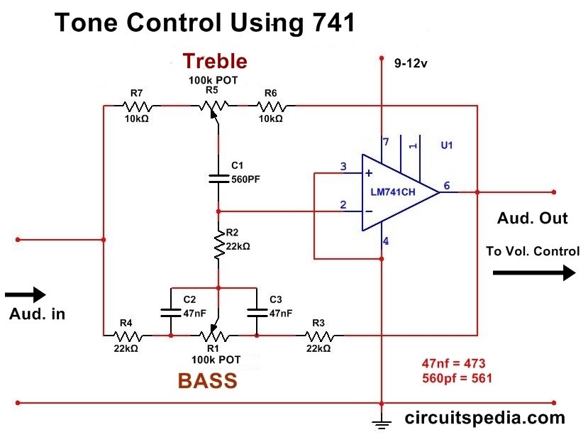
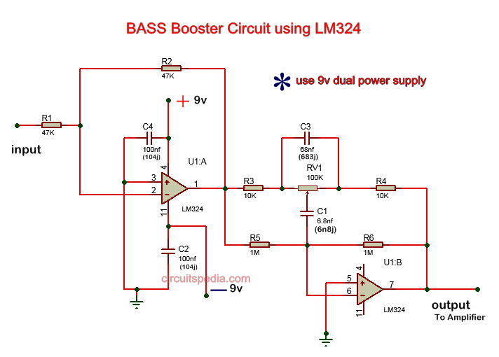
Here is Two Tone Control Circuit Diagram Which can be used to make A Tone Control At home Easily.
You Can Make This And Fix This For Your Homemade Audio Player Speaker. This is must before audio Level Controller .
The 1st Circuit used An Op-Amp IC 741 , Some PF capacitors And some resistors. Two 100K Variable resistor (is Used ) In Both Circuit.
It provides 15dB of Bass and Treble cut and boost with respect to the gain at the mid-frequency of 1000Hz. The output can be coupled to the next stage.
Circuit 1 Using OP-Amp IC 741
Circuit 2 Without Using IC
Must Read – How To Make Audio Amplifier


Good day! I just would like to give an enormous thumbs up for the great information you have here on this post. I will be coming back to your weblog for extra soon.
Very interesting information!Perfect just what I was searching for! “…obstacles do not exist to be surrendered to, but only to be broken.” by Adolf Hitler.
Please Provide one transistor tone control pcb layout and circuit diagram
Hello, my name is Mirko. I´m interresting for electronic and HF – Technik.
I´m a Radio Amateur at 1998 . My call sign is DL1BME .
By the Tone Control Circuit is the Resistor R5 ( 10K ) at the false position !
The Resistor R5 ( 10k ) must sitting after the Bass Controller and not by
the Treble Controler !
For better Tone Controls resultats all Resistors and Controlers 2,2 x higher !
The Resistors and Controler :
R1 = 22k / R2 = 220k / R3 = 2,2k / R4 = 220k / R5 = 22k
The capasitators are ok !
C2 = 10nF / C3 = 100nF ( Bass – Control )
C4 = 1nF / C5 = 10nF ( Treble – Control )
Thank you for reading.
Best greetings from Mirko ( DL1BME )
( 55+73 de DL1BME )
Bremen , Germany 15.08.2020