Distance measuring instrument design and development using Arduino UNO and Ultrasonic Sensor SR04
Distance measurement using ultrasonic sensor
Ultrasonic Sensor Interfacing with Arduino
Ultrasonic sensors not only offer distance-measuring utility without any physical contact but also enable us to measure with no noise and light, unlike laser-based distance-measuring instruments. Furthermore, these instruments are cheap and more reliable even in daylight, where laser-based instruments often decrease their efficiency. Distance-measuring instruments have been in use for centuries, and improvements have been made in their designs with the passage of time. Today, distance-measuring instruments such as foot rulers and inches tape are obsolete, and digital instruments are used for such purposes at a larger scale. High precision and more convenience of measuring any distance from one point have made the process easy. Such instruments are widely used at construction sites and for fluid level monitoring. In containers and sites where fluid level monitoring needs to be precise and remotely controlled, ultrasonic sensors based distance measuring instruments provide ease. Since the design is based on embedded systems and the whole process is controlled by a microcontroller, many features can be added to it. For example, remote transmission of fluid level and accordingly ON/OFF feature for a digital fluid switch.
Theory
Arduino UNO microcontroller has gained popularity for its vast library and easy programming. The digital and I/O pins with multiple timers have enabled us to design and develop complex projects with ease. Arduino UNO board is compatible with various sensors and offers exceptional efficiency at a low cost. The microcontroller is a free source design and one of the most demanding boards in the World.
Ultrasonic sensor working
Ultrasonic sensors, also known as Sonar sensors, have been in use for decades. They were once used for the mapping of ships in the sea and the detection of broken/faulty parts in mechanical systems. The ultrasonic sensor works by transmitting ultrasonic waves, and these waves strike obstacles placed in front of the transmitter. The waves are reflected and hit the receiver. The time taken by the waves from transmission to receiving with respect to the velocity of ultrasonic waves is used to measure the distance of obstacles present ahead.
The HC-SR04 ultrasonic sensor is a popular choice for distance measurement, obstacle detection, and automation. This sensor operates on the time-of-flight principle, using ultrasonic sound waves to detect objects with high accuracy.
What is the HC-SR04 Ultrasonic Sensor?
The HC-SR04 is an ultrasonic ranging module that measures distances without physical contact. It works by emitting high-frequency sound waves and calculating the time taken for the echo to return.
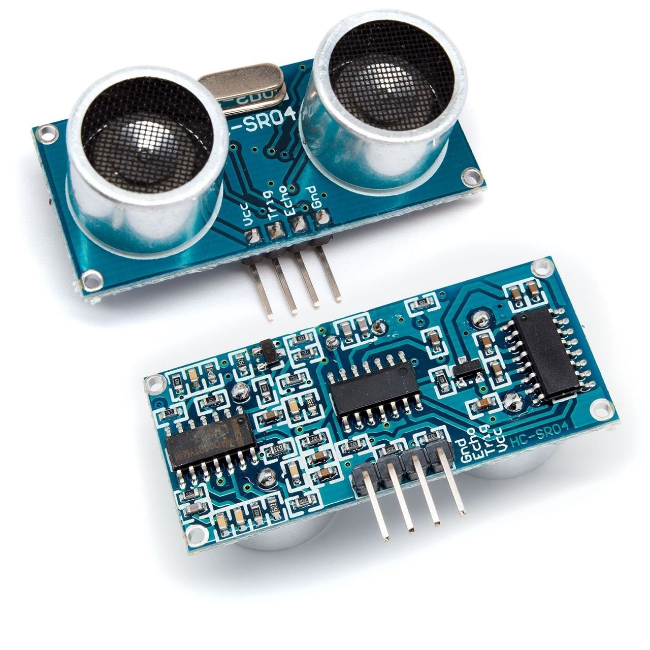
HC-SR04 Sensor Pin Configuration
The sensor has four pins:
- VCC → Connect to 5V DC power
- GND → Connect to Ground (0V)
- Trig (Trigger) → Sends the ultrasonic pulse
- Echo → Receives the reflected sound wave and outputs a signal
Inside the sensor, two key components work together:
✅ Ultrasonic Transmitter → Emits a 40 kHz sound wave
✅ Ultrasonic Receiver → Detects the reflected wave (echo)
How Does the HC-SR04 Work?
The HC-SR04 sensor operates in four simple steps:
1️⃣ Triggering the Sensor
- The Trig pin is given a HIGH signal for 10 microseconds (µs).
- This prompts the ultrasonic transmitter to emit an 8-cycle 40 kHz ultrasonic pulse into the air.
2️⃣ Sound Wave Reflection
- The emitted sound wave travels forward.
- If it hits an object, it bounces back toward the sensor.
3️⃣ Echo Signal Generation
- The Echo pin stays HIGH for the duration it takes for the ultrasonic wave to return.
- The pulse width of the Echo signal corresponds to the round-trip time of the sound wave.
4️⃣ Distance Calculation
Using the speed of sound in air (~343 meters per second), the distance (D) is calculated as
D=Speed of Sound×Time/2
Since the sound wave travels to the object and back, we divide by 2 to get the one-way distance
Example Distance Calculation
Let’s say the Echo pin stays HIGH for 5000 µs (5 milliseconds):
- Convert to seconds: 5000×10−6=0.005 S
- Calculate distance:
D=343×0.005/2=0.8575 meters(or85.75cm)
So, the object is 85.75 cm away from the sensor!
How It Works:
✔ The Trigger pin sends an ultrasonic pulse.
✔ The Echo pin measures the return time.
✔ The distance is calculated and displayed on the Serial Monitor.
Real-World Applications of HC-SR04
🔹 1. Obstacle Avoidance (Robotics & Drones)
Robots and drones use ultrasonic sensors to navigate and avoid obstacles in real time.
🔹 2. Smart Parking Systems
Used in car parking sensors to detect nearby objects and prevent collisions.
🔹 3. Water Level Monitoring
Measures the water level in tanks without any physical contact.
🔹 4. Security Systems
Detects unauthorized movements and triggers alarms in intruder detection systems.
🔹 5. Distance Measurement & Industrial Automation
Used in conveyor belt automation, object counting, and more!
Advantages & Limitations of HC-SR04
✅ Pros:
✔ High Accuracy (~1 cm)
✔ Non-contact measurement (Ideal for delicate applications)
✔ Affordable & Easy to use with microcontrollers (Arduino, Raspberry Pi)
❌ Cons:
❌ Temperature Dependent (Speed of sound changes with temperature)
❌ Not effective on soft materials (Foam, cloth, etc., absorb sound waves)
❌ Limited range (Max 4 meters)
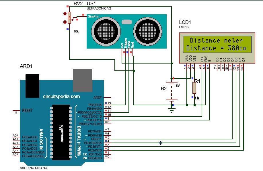
Since the distance can’t be changed physically in the simulation, the simulation model of SR04 is connected with a potentiometer, and the distance for the sensor is varied using this potentiometer.
Ultrasonic Sensor Range
HC SR-04 Ultrasonic Distance Sensor Provides The Range between 2cm to 400 cm approx (1 inch to 13 foot). With Fully non contact .

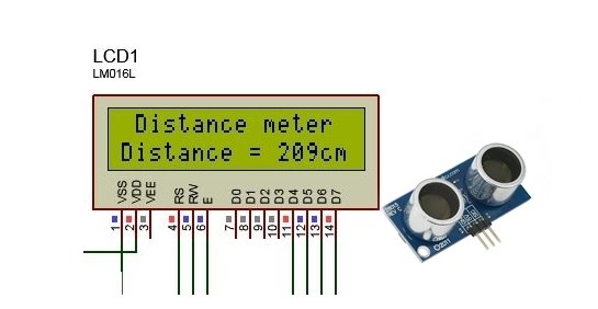
Measurement of distance needs to be expressed in some way, and for embedded systems, the best way is to use an LCD. The 16×2 HDD44780 driver-based LCD offers efficient and smooth functioning at a cheap price. The 16 columns and 2 rows offer enough space to display the results. The LCD is compatible with all models of Arduino boards, which makes it suitable for this project, too.
Components required
- The components required for this project are simple and low cost.
- Arduino UNO MCU
- Ultrasonic sensor SR04
- 16×2 LCD (HDD44780 driver based)
- 6v battery or 5v USB power source (Mobile adapter/laptop)
- Potentiometer 10k ohm
- Jumper wires
- Breadboard
Connection Diagram
Simulation
Proteus 8-based simulation model has been demonstrated here. This simulation enables designers and developers to verify a circuit’s functioning before proceeding towards hardware design. Directly developing hardware on PCB or veroboard can be stressful if the end product fails to run due to misplaced connections. Simulation helps in tracking mistakes and improving designs, you can always add more creativity to your design and test it on simulation. The simulation models used for Arduino UNO and the Ultrasonic sensor in proteus are easily available on the internet. The only effort needed is to connect all components as described in the circuit diagram.
The working mechanism of this project is simple and easy to understand. The ultrasonic sensor has 4 pins, out of which 2 pins are for power, and the remaining 2 pins are for the trigger and echo. The MCU transmits ultrasonic waves through the trigger pin and then reads the receiving time of that ultrasonic wave on the echo pin. The velocity of the ultrasonic wave traveling is defined, and accordingly, the distance is measured.
It is essential to add a hex file of Arduino code in its simulation model. The hex file is in the form of binary instructions given to the MCU for processing.
LCD serves as a graphical interface for displaying results. The display brightness can be adjusted by supplying 0-5v on pin 3, which is unnecessary in case of simulation but works well for hardware design. Make sure the pins are carefully connected with Arduino, as mentioned in the circuit diagram.
The use of the 10k Preset is only in simulation for making an Object between sensors. Here, the preset is works as an object.
The use of a potentiometer with the Ultrasonic sensor enables the user to control the input distance for the sensor and observe changes in results accordingly. The value of this potentiometer must be above 1K ohm.
Since the simulation model ensures proper functioning of the design, if your simulation works correctly, you can proceed toward the development of the hardware design. However, in case if your simulation is not working correctly, you need to troubleshoot your error.
If your LCD is displaying distance and it varies, but the distance is incorrect, you might be directing your Ultrasonic sensor in the wrong manner. make sure the path is clear between the target obstacle and the Ultrasonic sensor and that the sensor is facing the obstacle. Alternatively, the connections of the ultrasonic sensor with Arduino might be wrong. If there is no display on the LCD, then you need to check the code and connections of the LCD with Arduino.
If you fail to connect all components as instructed in the circuit diagram, the simulation might not work or show unexpected behavior..
Coding
The coding has been compiled on Arduino IDE. The code starts with the LCD library. The pin connection for LCD and Arduino UNO are defined for proper communication. Then, all components and pins used are defined.
The setup function is where the baud rate is defined and the selection between Input/Output functioning of pins is made. The LCD size 16×2 is defined here, and initially few commands are used for clearing LCD..
The loop function contains the main body of instructions. It keeps iterating for as long as the MCU runs. The whole mechanism of ultrasonic-based measurement is processed here using multiple commands. The distance is calculated after computations is displayed on the LCD using commands.
Ultrasonic sensor arduino code
#include <LiquidCrystal.h>;

LiquidCrystal lcd(10,9,5,4,3,2);

const int trigPin=13;  // defines the pin numbers
const int echoPin=11;

long duration;                // defines variables
int distanceCm, distanceInch;


void setup() {
  Serial.begin (9600);
  lcd.begin (16,2);     // Initializes the interface to the LCD screen, and specifies the dimensions (width and height) of the display
  pinMode (trigPin, OUTPUT);
  pinMode (echoPin, INPUT);

  }

void loop() {
digitalWrite(13,LOW);  // Clears the trigPin
delayMicroseconds(2);
digitalWrite(13,HIGH); // Sets the trigPin on HIGH state for 10 micro seconds
delayMicroseconds(10); // Sets the trigPin on HIGH state for 10 micro seconds
digitalWrite(13,LOW);


duration = pulseIn(11, HIGH);   //To receive the reflected signal.

distanceCm= duration*0.0340/2;  // Calculating the distance
distanceInch = duration*0.0133/2;

lcd.setCursor(0,0);      // Sets the location where text written to the LCD will be displayed
lcd.print("Distance= "); // Prints string "Distance" on the LCD
lcd.print(distanceCm);   // Prints the distance value from the sensor
lcd.print(" cm    ");
delay(20);
lcd.setCursor(0,1);
lcd.print("Distance= ");
lcd.print(distanceInch);
lcd.print(" inch    ");
delay(20);

}


Good night sir, i like your news site ! Have a nice weekend