Easy, Simple and best FM transmitter circuit for homemade mini radio station
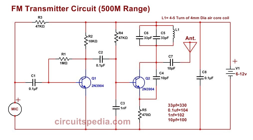
Homemade FM Transmitter circuit diagram
Components
Transistor- 2N3904-2
Resistor-1M-1, 470Ω-1, 22k to 47kΩ-2, 10kΩ-1
Capacitor-1nf-1, 0.1uf-3, 10pf-2, 33pf-2
Inductor- 4-5 Turn of 4 mm dia air core coil of copper wire
Condenser mic-1
This simple and easy FM transmitter circuit can transmit the input signal gets from the microphone up to the 500-meter range area. Two NPN transistors and some discrete components are used in the circuit.
This FM Transmitter Circuit is a simple two-stage transistor-based transmitter designed to transmit audio signals over FM frequency up to a 500-meter range. It operates at a voltage range of 6V to 12V and uses 2N3904 NPN transistors as the key components.
You can use a 9v to 12v DC power supply for this circuit. At low voltage, the range of this transmitter will be shorter. At high voltage range will also be increased.
In this FM transmitter, there is no variable capacitor used for tuning by the change of capacitance, So the frequency will remain constant if the input power supply does not fluctuate. This is a simple circuit and can easily be constructed at any general-purpose Vero board or PCB board. For more stability of frequency, don’t use ac adaptor, use the only battery, and all connections are insulated from external touch. Use only the Battery to give the power supply to the stable operation of the circuit. The condenser mic hs polarity, so check the polarity before connection.
| Component | Function |
|---|---|
| MIC (Microphone) | Captures sound and converts it into electrical signals. |
| C1 (0.1µF Capacitor) | Blocks DC and allows AC (audio signal) to pass from MIC. |
| R1 (1MΩ), R2 (10kΩ) | Biasing resistors for Q1 to amplify weak microphone signals. |
| Q1 (2N3904 Transistor) | First stage amplifier that boosts weak audio signals from MIC. |
| C2 (0.1µF Capacitor) | Coupling capacitor that transmits the amplified signal from Q1 to the second stage. |
| Q2 (2N3904 Transistor) | RF Oscillator, modulates the frequency for transmission. |
| L1 (4-5 turns, 4mm Air-Core Coil) | Inductor forming a tank circuit for frequency generation. |
| C3 (1nF), C4 (10pF), C5 (33pF), C6 (33pF), C7 (10pF) | Capacitors used in the oscillator circuit to determine the transmission frequency. |
| R3 (47kΩ), R4 (47kΩ), R5 (470Ω) | Resistors for biasing and stability. |
| C8 (0.1µF Capacitor) | Power supply filter capacitor to reduce noise. |
| Antenna (Ant.) | Enhances the transmission range. |
| V1 (6-12V Power Supply) | Powers the entire circuit. |
⚙️ Circuit Working & Operation
Step 1: Audio Signal Processing (Pre-Amplifier Stage – Q1)
- The MIC (Microphone) captures the sound and converts it into an electrical signal.
- C1 (0.1µF) allows the AC signal to pass and blocks DC.
- Q1 (2N3904) acts as an amplifier to boost the weak microphone signal.
- The amplified signal is sent through C2 (0.1µF) to the next stage.
Step 2: Frequency Modulation & Oscillation (Q2, L1, C3, C4, C5, C6, C7)
- Q2 (2N3904) is configured as an RF oscillator to generate a high-frequency carrier wave in the FM band (~88-108 MHz).
- The tank circuit (L1 & C5, C6, C4) determines the transmission frequency.
- The modulated audio signal from Q1 is superimposed on this carrier frequency, resulting in Frequency Modulation (FM).
- C7 (10pF) acts as a coupling capacitor to the antenna for better transmission.
Step 3: Transmission via Antenna
- The modulated RF signal is transmitted via the Antenna.
- The transmission range depends on power supply, antenna length, and tuning of L1 & C5/C6 capacitors.
📡 Applications
- Wireless FM Microphone
- Spy Bug Transmitter
- Remote Audio Transmission
- Short-range FM Broadcasting
🛠️ How to Improve Performance?
✔️ Use a longer antenna (30-50 cm) for better range
✔️ Ensure stable power supply (9-12V)
✔️ Adjust L1 coil turns & C5/C6 values to fine-tune the frequency
Also read


Hello sir, can i use another resistor instead of 1M ohm resistor
check 470K or 220K resistor
Hello,
I was looking for a simple and easy to build FM transmitter which uses accessible parts and came across your design which seems very great! But I have one Question. What kind of values should the two Capacitors C5 and C6 have, in order for the transmitter to transmit at a frequency of 87.5mhz? As this is the only legal FM frequency to use in the country I live in.
Thank you.
Hello,
If I may ask another Question, what is the current draw of this Fm Transmitter under normal use
Thank you.