What is NOT gate (Inverter)
NOT gate logic inverter circuit
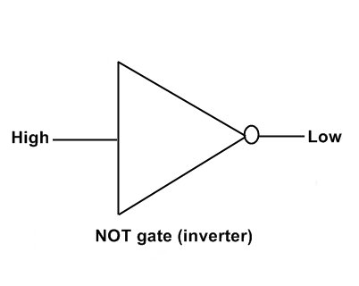
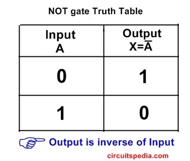
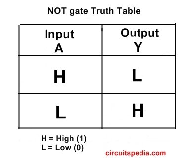
NOT gate is a Device that gives output always the inverse of the input. NOT gate output is always the complement of its INPUT. NOT gate, also called an INVERTER, which has only one input and only one output. The main function of the inverter (NOT gate) is the invert the input signal at the output. The output signal is inverted from the input signal. Low input gives a high output and vice versa.
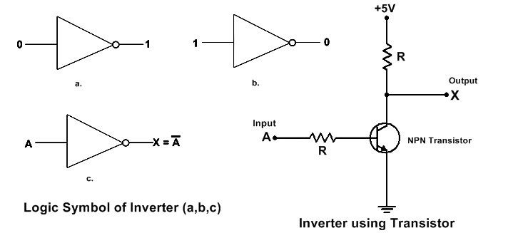
• In the NOT gate, if the input is 1, then the output is 0, and if the input is 0, then its output is 1. Here, 1 means the Positive supply or High state. 0 means 0V supply or LOW state.
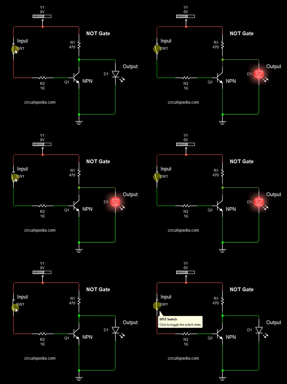
• We assume that in any NOT gate circuit, we connect the input to +5V; this +5V input is HIGH and logically 1. Then the output of it is 0V, which means logically 0.
• At input if there is a 0V supply. It means input is 0 (LOW), then the output of the NOT gate is +ve (HIGH). Logically 1, and here we use 5V, then the output is 5V.
• In other words, when the input is OFF, then the output gets ON, and if the Input is ON, then the Output remains OFF.
The output of the NOT gate is represented by A- (A bar). If the input is A and the output is X, then the expression for the output is X=A-.
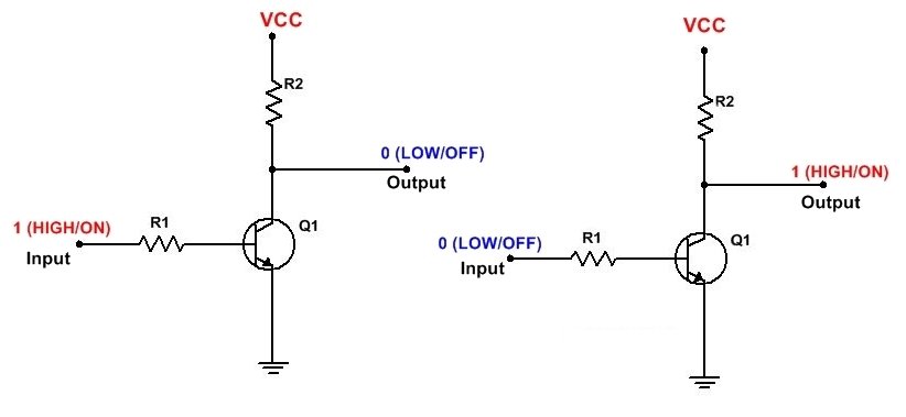
Not gate may be made using the connection of one transistor and two resistors as shown in the figure. This method of Realization of the gate is called RTL (Resistor Transistor Logic).
When the Input is 0V, then the transistor is OFF, and the output, which is connected to the collector, gets current through the resistor R2. When the Switch is turned on and there is a supply given on the Base of the transistor, then the transistor is turns on and current passes between the emitter and collector and All voltage is dropped on R2, which comes from VCC, and therefore the output is 0V, meaning the output gets turned Off.
NOT gate Inverter Logic circuit using transistor
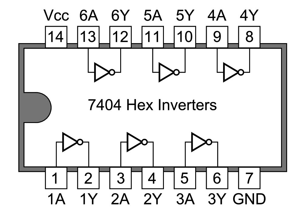
In one chip, there are no gates included in a single IC. The IC 7404 is made for the operation of a NOT gate (INVERTER). 7404 IC has 6 NOT gates. The IC 74LS04 is a Hex inverter IC. These ICs contain six independent inverters.

