

Dark/Light Activated Circuit using LDR
The dark sensor circuit is very useful to automatically switch ON and OFF any appliance by Detection of Light and Dark. LDR is a photoresistor that is used for the detection of light. When Light intensity is high on LDR, The Resistance through it decreases, and When Light intensity is Low on LDR, then the resistance through it will increase and go very High. This Property is very useful in the operation of Dark Detector circuits. LDR is a Light-dependent Resistor. LDR is a special type of Variable resistor whose value can be increased or decreased according to light falling on it. As its specified property, LDR acts as the light and Dark sensor. When Light falls on LD,R the Resistance of it goes very high in MEGA OHM.


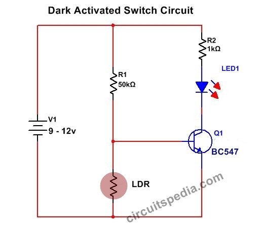
Here is a Simple Dark sensor Circuit that can be used as an automatic Switch On And Switch Off Any Load Using a Relay. Here, I am presenting a simple circuit using only resistors, LDR, and transistors, but Many Types of circuits can be constructed using LDR for Dark detected switching. This Simple and best Dark Activated circuit uses one NPN transistor to turn on or off according to the light sensed by the LDR. You can use a Variable resistor at the place of 50K for the adjustment of sensitivity.
When Light falls on LDR, then the internal resistance of LDR will minimum, and all voltage coming through R1 dropped with the ground and become 0V, then no sufficient power at the base of the transistor get to turn on and light is switched off. At Dark Resistance will be Very High and very less power dropped with the ground because of LDR holds by high resistance and transistor gate terminal get sufficient voltage to turn ON and the Light is switched ON
At Day-When Light intensity High, the connected load remains to Switch off. At Night, when the light intensity is negligible, the light is automatically switched ON.
Schematic diagram 1

If you want to connect any high load or AC, then you need to use a Relay. The circuit diagram shows the Relay connection with the Dark Activated automatic Light switch. Use DC supply 0f 9-12v for the circuit operation or use any adaptor or can be used homemade AC to DC converter for circuit input. If BC547 gets Hot And is not able to handle the relay, then you can use 2N222A transistor Or SL100. But If you use Small size Pcb Relay then BC547 can handle easily. These circuits are very useful in the automatic street light.
Schematic diagram 2

LDR-1
Transistor Bc547 or 2N222A-1
Resistor 50k-1 or Preset 100k-1, 1k-1
Relay-1 (9v) 6A
LED-1
Diode 1N4007-1
Also Read
-
Delay ON Timer using Transistor
-
Dual colour LED Chaser / Flasher Circuit
-
Zener diode
-
How does a Relay Work


 13")


Exactly what I was looking for, thanks for posting.
high fi ampliflayer with 2000 watt matareal and circute all componatns rs pease tall me