kirchhoff’s law
Contents
Kirchhoff’s voltage law
(KVL)
According to Kirchhoff’s Voltage Law (KVL), In any closed circuit or mesh, the algebraic sum of all the emf (voltage source ) and all the voltage drops is zero. This Law deals according to the principle of conservation of energy, and according to the principle of conservation of energy, Net energy supplied must be Equal to Net energy consumed or Net energy consumed must be equal to Net energy supplied. This means the total amount of voltage available in any circuit is the exact same as the total drop voltage in that circuit.
If you know the supply voltages in the circuit then you can find the unknown quantity in the circuit by applying the KVL., and The KVL works in 2 types of voltages – Voltage rise and voltage drop.
What is Rise in potential and drop-in potential?
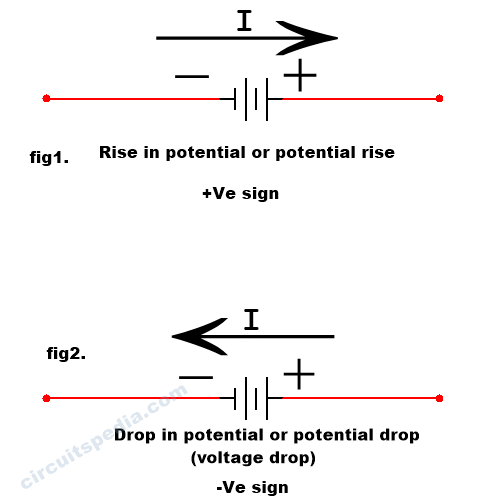
As shown in Fig. 1. The direction of flow of current is denoted from the higher potential to the lower potential.- This is called a Rise in potential or Potential rise. This is always denoted with a +ve sign.
In fig 2. the direction of flow of current is denoted from lower potential to higher potential. This is called a drop in the potential or a potential drop, we also call it a voltage drop. This is always denoted with a -ve sign.
kirchhoff’s current law (KCL)
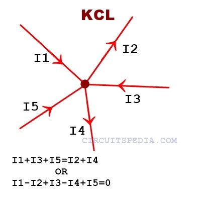
Kirchhoff’s current law- According to Kirchhoff’s current law, the algebraic sum of all currents meeting at a point or a junction will be zero. This law is based on the principle of conservation of charge. According to the principle of conservation of charges, the Net charges dissipated from the junction or a point are exactly equal to the Net charge provided to the junction. This means the amount of output current is the same as the total amount of input current you provided.
Mesh
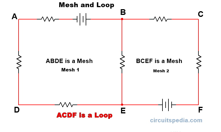
Mesh is the closed path of an electrical circuit through which current can flow, but through that closed path or across the closed pat,h there is no other closed path inside it.
In the given diagram, ABDE can be called a Mesh, and BCEF can also be called a Mesh because both a closed path and no other closed path inside it.
Loop
A loop is a closed path of an electrical circuit through which current flows, but various other closed paths are contained inside it.
Difference between Loop and Mesh
A Mesh is a closed path only, no other paths are contained inside a Mesh But there are various small paths that may be contained in a loop. This is the difference between Mesh and Loop.
Examples
Example 1
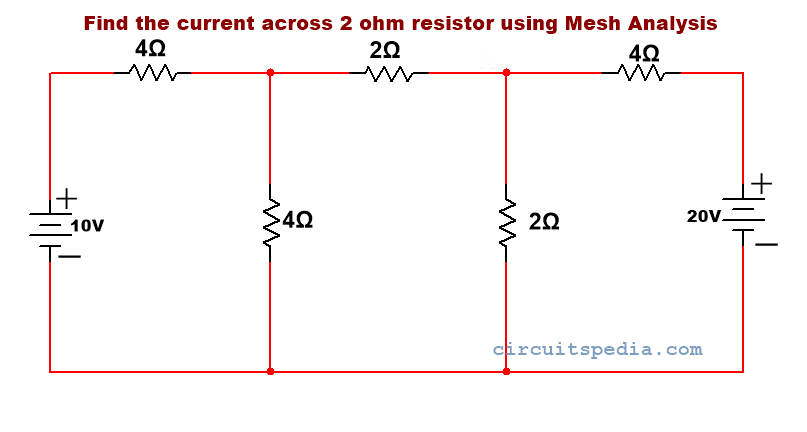
Q1. Calculate the current through the 2 Ω resistor using the Mesh analysis method.
solution-
Step 1 – Identify all meshes in the circuit
Step 2 -Directions assigned in all meshes. clockwise or anticlockwise as you like. But the directions of all meshes are in the same direction.
Step 2 -Apply KVL in each mesh and identify equations for each.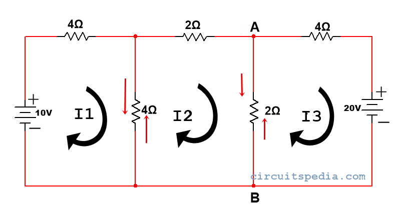
Applying KVL in mesh 1
Here the direction is from lower to higher potential
so, 10-I14-4(I1-I2) = 0
Because current goes through a resistor, there is always a voltage drop in the resistor. So, I14 is in the -ve sign. And in another 4Ω resistor, there are two directions of current, in mesh 1 from upper to lower and in mesh 2 from lower to upper .so, here we write 4(I1-I2).
10-4I1-4I1-4I2=0
or, -8I1-4I2=-10—–eq1
Applying in mesh 2.
–2I2-2(I2-I3)-4(I2-I1)=0
-4I2-2I3-4I2-4I1=0
-8I2-2I3-4I1=0—–eq2
Applying KVL in mesh 3.
here the direction is higher to lower on 20v supply so,
-20-2(I3-I2)-4(I3)=0
-6I3-2I2=20—–eq3
By solving eq1 ,2 and 3
I1=1.093A
I2=-0.312A
I3=-3.43A
Now we have to find the current from the 2Ω resistor, there are 2 currents, I2 and I3, flowing through point A and Point B.
So, IAB= I2-I3 {because here value if current I2 is greater than I3)
IAB=-0.312-(-3.43)=-3.125A
Ad
Examples based on KCL (Node analysis Method)
Steps for solving the question.
Step1. Identify the principal nodes or junctions present in the network
Step2. Assign a junction potential on each junction with respect to the assigned reference junction, having value Vo=0V (practically grounded)
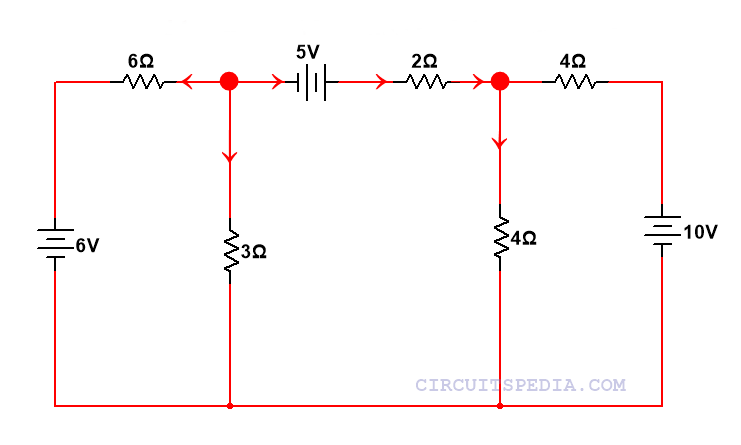
Step3. Assuming all the current is in the outgoing direction from each junction (You can assume incoming current). Form KCL equations
Step4. Solve the equations to calculate the value of junction potentials
Step5. Using individual junction potentials, find the value of the required electrical quantity.
Example 2
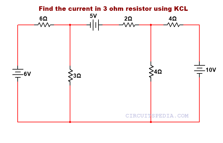
Q2. Find the current in 3Ω resistor using KCL.
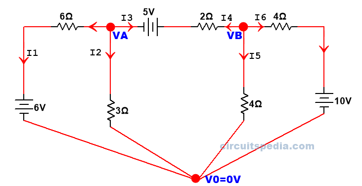
As Step 1 and Step 2, identify the principal node in the network. So, I got a total of 2 junctions in here. We denoted as VA and VB ,and assigned a reference junction with V0=0V
we can also see this circuit as below
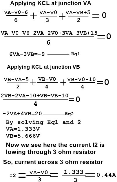
Step 3. Assuming all current outgoing directions on each junction and forming the equations by applying KCL
Example 3
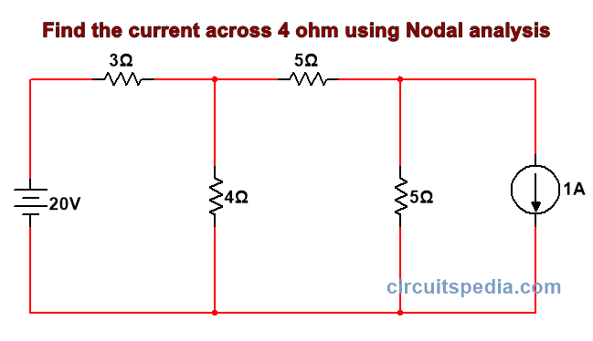
Q3. Find the current across 4Ω resistor using Nodal analysis
Solution-
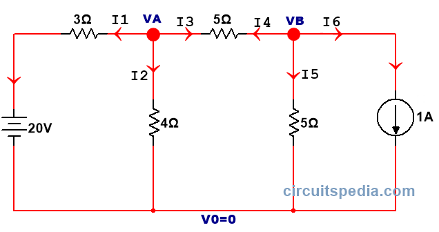
Step1. Identify all junctions
Step2. Assign junction potential at each junction concerning the reference junction, assign V0=0V
Step3. Assume the current flowing outgoing of each junction
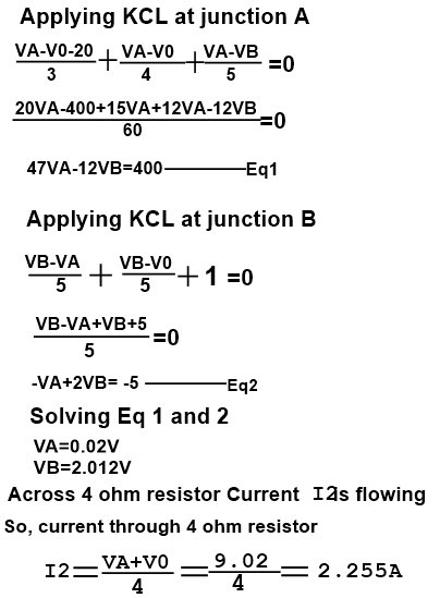
Step 4. Solve the equations to calculate the value of junction potentials
Also read

