Loading [MathJax]/jax/output/HTML-CSS/config.js
Skip to content

  • About us
  • Submit a Post (Guest Post)
  • Electronics MCQ online test
  • Services
  • Uncategorized
  • YouTube Video Gallery
  • Tools-Calculator/Converter
    • LM317 ic voltage regulator Resistor Calculator
    • THrough hole resistor color code calculator
    • SMD resistor code calculator
    • Watt to ampere converter | Power to current conversion
    • Capacitor unit converter
    • Capacitor code to value and value to code converter
    • Capacitor Series and Parallel Calculator – Instantly Calculate Total Capacitance
    • Resistor Series and Parallel Calculator
    • Battery Charging Time Calculator
    • Ohm’s Law Calculator
    • 555 Timer Calculator: Astable & Monostable
    • Voltage Divider Calculator & Rule-Online Tool
    • Low pass filter Calculator
    • Wire Size Converter: AWG to MM, CMIL, Inches
    • Number System Converter | Decimal, Binary, Hex, Octal
    • dBm to Watt Calculator
  • Datasheet
  • Home
  • 12v Lead acid Battery charger with Autocut
  • 12v Battery Charger circuit with Overcharge Protection
12v battery charger auto cut circuit

12v Battery Charger circuit with Overcharge Protection

10 Comments / 12v Lead acid Battery charger with Autocut
Spread the love

12v Battery Charger Circuit with Overcharge Protection

Contents [hide]

    • 12v Battery Charger Circuit with Overcharge Protection
  • 12v battery charger with auto cut-off circuit diagram
  • Schematic diagram 
    • circuit 1
    •  10 amp battery charger circuit diagram
    • Circuit 2
    • Circuit 3

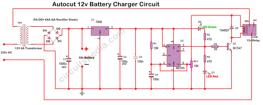
This 12-battery charger circuit provides an Automatic cut-off facility when the battery gets fully charged. Before using this circuit, you need to adjust the Cut voltage range for the auto cut. This adjustment is done by moving the 10k preset, and for testing the output voltage auto cut range, a multimeter is connected to the output terminals that go to the battery. This voltage range can be set by using any 13v or 14v DC supply that connects the terminals that go to the battery. And moved the preset till the green led ON. Once the auto-cut voltage is set, the circuit is ready to use. 

One terminal of Input AC power to the Transformer is connected through a 12 V Relay. When the Battery needs charge then the Red LED glow. When the Charge level goes to about 12v or 13v, then the Red LED will turn off, and the Green LED will glow. And the Input Power to the Transformer of the charger is also disconnected by the Relay. 

12v battery charger with auto cut-off circuit diagram

One 555 timer ic is used for detecting the voltage level, and a Relay is used to disconnect the AC input. 7808 voltage regulator is used for constant supply to the operation of the circuit to cut at a required fixed voltage.

This 12v battery charger automatically cuts the circuit after a full charge and provides 6 Ampere high current, and this can use for a big-size Lead-acid Battery up to 100 AH. If you want more higher current, then replace the transformer with 10A and use a 10A10 Diode. You can use a ready-made 12v  10 A Bridge Rectifier, which is available in the market.

Schematic diagram 

circuit 1

how to make a 12v battery charger

Components

Diode

6A8 or 6A10- 4 pc

1N4007 – 1

7808 ic – 1 pc

555 timer ic – 1 pc

Capacitor

1000uf 50v – 1pc

1000uf 25v – 1pc

100nf (104) – 1 pc 

Resistor

10K – 1

5k – 1

470 Ω – 2 

Relay 12v 6 A – 1

Preset 10k – 1 pc

LED 1 pc – Green

LED 1 pc- RED

Transistor BC547 -1 pc


 10 amp battery charger circuit diagram

Circuit 2

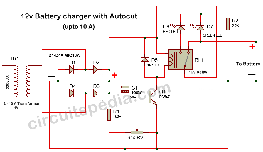
Connect positive output wire on NC through Common pin of Relay


autocut off 12v battery overcharge protection

Parts (circuit 2)

Transformer 0-14V (10A)-1

Diodes

MIC10A-4

1N4007-1

Capacitor 1000uf 50v – 1

Resistors

2.2K-1,  150R-1

Preset RV1-10K-1

Transistor BC547B-1

Relay 12v (10A)- 1

LED- 2 ( Green -1, Red-1)

Circuit 3

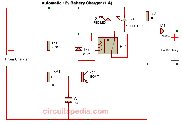
This circuit has a maximum current capacity of 1 A only.

12v battery charger circuit diagram

Also read

Delay Timer To Switch ON / Switch OFF

LED Chaser Flasher Circuit

Automatic water level controller

230v ac to 12v dc and 5v dc Regulated Power Converter

Dimmer/Fan regulator circuit


Spread the love
← Previous Post
Next Post →

10 thoughts on “12v Battery Charger circuit with Overcharge Protection”

  1. Anonymous
    July 30, 2019 at 11:18 pm

    What is mosfet, ? thet i know no.

    Reply
  2. Freeborn Umukoro
    January 23, 2020 at 1:58 am

    I built a 2kva inverter, and now I need a circuit that can charge a 100 amps battery

    Reply
  3. Yogesh Sambare
    January 27, 2020 at 10:39 pm

    hello, sir I have one question?
    how can we make auto on battery charger when the battery is low

    Reply
  4. Siddaraju
    February 2, 2020 at 4:40 pm

    Hi sir,

    I am designing a lead acid battery charger with autocut off feature.
    I build a circuit as mentioned in your website (upto 10A circuit).

    Currently I am using 12-0 transformer and bc 547 for auticutoff and 10k pot for to set cut off voltage.

    I set a cut off voltage at 13.5 volt but while setting 13.5v I have faced some issues due to hanging wires now it’s resolved but still 10k pot resolution is very less I can’t able to set exact value simply if I just touch the pot cut off voltage will jump 1v like that.
    For example from 13.5v cut off voltage to 13.7v I am unable to set it small rotation will go more than 14v so please let me know how you selected 150 resistor and 10k pot in the design and also let me know by changing this value I can achieve more resolution or not.

    And also I have one more query like to set cutoff voltage I am used fully charged lead acid battery is there any easy way
    Is there to set the cut off voltage
    (In some video they will connect multimeter and they set the cut off voltage but if I connect multimeter it will showing maximum voltage only so I can’t able to set cut off voltage)
    In circuit I added one switch (on/off)and one 5A diode(reverse protection)

    I am building 3A,13.5v cutoff lead acid battery charger so please help me as soon as possible.

    Reply
    1. Admin
      February 2, 2020 at 6:16 pm

      Thanks for sharing your experience and difficulties in making this.
      If many times relay not active at a fix voltage level, then adjust the pot some below or some high than 12 v
      Keep in mind The step-down transformer is of higher than 12v. you can use 14v or 15 v transformer

      Reply
  5. Pingback: Car Battery Used Acid - EZ Battery Reconditioning

  6. anonymous
    May 11, 2024 at 2:34 pm

    “WOW, I’m so impressed with the circuit diagram! It’s really detailed and helped me understand how to build my own 12v battery charger with auto cut off. I had been searching for this kind of information online for weeks. Thank you so much for sharing this!

    Reply
  7. Phil
    April 24, 2025 at 7:37 pm

    Hi,
    I designed the battery charger with the 7808 voltage regulator.
    How can the 12V relay operate with an output voltage of 8V max and even lower via the 10K pot?
    Thanks for your help.

    Reply
    1. Admin
      April 26, 2025 at 1:02 pm

      if you want to use 12v relay with the 8V power, it may fail to trigger the relay coil, with 8v Power you should use 9V relay and which type circuit do you wqant to use. Please clear your required circuit design specification.

      Reply
  8. Rejekibet
    April 25, 2025 at 8:13 am

    This circuit diagram is fantastic! I never knew a 12V battery charger could be so simple yet effective. The auto cut-off feature is a must-have for safeguarding my batteries. Thanks for sharing such valuable information!

    Reply

Leave a Comment Cancel Reply

Your email address will not be published. Required fields are marked *

  • 12v Lead acid Battery charger with Autocut
  • 4017 Counter
  • 555 timer
  • A Guide For Electrical Safety
  • Arduino projects
  • Audio Amplifier
  • Capacitor Code
  • Clap operated switch
  • Classification of electrical elements
  • Dark sensor Circuit
  • Datasheet
  • Delay Timer To Switch ON / Switch OFF
  • Diff between 12-0-12 and 0-12 transformer
  • Difference btwn electrical and electronics
  • Digital Object Counter
  • Dual power DC supply circuit
  • Electronics Multiple choice question MCQ online test
  • Fan Regulator/ AC-DC Dimmer
  • Flip Flops
  • Fm transmitter
  • Fusible resistor working
  • high voltage protection circuit
  • how capacitor block dc current
  • How does a Relay Work
  • Indicator
  • Inverter Circuit
  • kirchhoff's law
  • LED bulb circuit
  • LED Chaser Flasher Circuit
  • Light switch wiring for Tunnel,Godown,Hostel etc
  • LM317 Calculator
  • Logic gates circuit
  • Melody generator/ Door bell alarm
  • Mobile Phone Detector
  • Mobile Phone Jammer
  • Motion Sensor Project
  • Norton's Theorem
  • number system
  • obstacle detector/Infrared proximity sensor circuit
  • ohm law
  • Online resistor color code calculator
  • Push ON push OFF switch
  • Rectifier circuit
  • regulated power supply
  • Remote controlled
  • Resistor Color Code
  • Sample and Hold circuit
  • Security Alarm
  • Semiconductor device numbering system
  • Servo motor control using Arduino UNO
  • Stabilizer Circuit Diagram
  • Thevenin theorem
  • Tone Control (Bass-Treble)
  • Tools-Calculator/Converter
  • Touch Switch
  • Transistor Working Principle
  • Uncategorized
  • water level controller
  • What is Comparator
  • What is DIAC
  • What is Impedance & Reactance
  • What is Operational Amplifier
  • What is Optocoupler
  • What is PIN diode
  • What is Surface mount technology (SMT)
  • What is zener diode
  • What is Zero Crossing detector

Copyright © 2025      Tools-Calculator | SERVICES | HOME 

  • Privacy policy
  • About us
  • Disclaimer
  • Services
  • Home