Relays are used for multiple applications ranging from flashing a small lamp to switching a high-watt AC motor or any other similar functions.
In this guide, we will study relays, their uses, components, types, working principles, and relay connection procedures. Let’s start the discussion.

Defining the Term “Relay”
- A relay is an electromagnetic switch that gets triggered whenever a slight current is passed through its coil.
- A surprising reality is that this slight current can turn on a secondary circuit that functions on a much larger current.
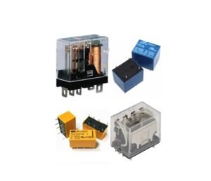
- In the electronics industry, there is a diversity of relays accessible that work at varying voltages.
- While building your circuit, the voltage ratings should be considered which will activate it.
What is the Purpose of a Relay?
Relays are extremely helpful when applied in the controlling setting. As suggested by the name, several sensors are highly sensitive electronic elements. Hence, they generate only slight output currents. However, there is a need to get large electrical equipment through those sensors. Herein, relays enable small currents to activate large current circuits.
What are the Components of a Relay?
Before we talk about it, let’s understand an electromagnet. It is defined as any current-transmitting conductor which induces a magnetic field, The iron core becomes highly magnetized when the conductor covers across an iron core in an electromagnet.
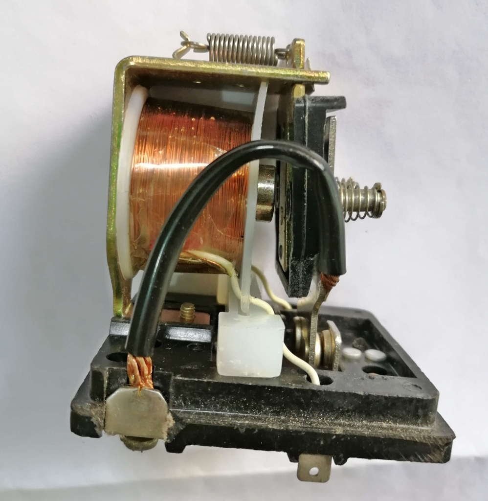
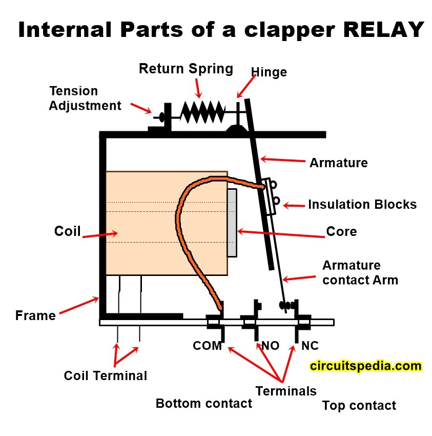
The internal construction of a relay
- The coil is a significant part of a relay. This coil functions as an electromagnetic switch for the relay.
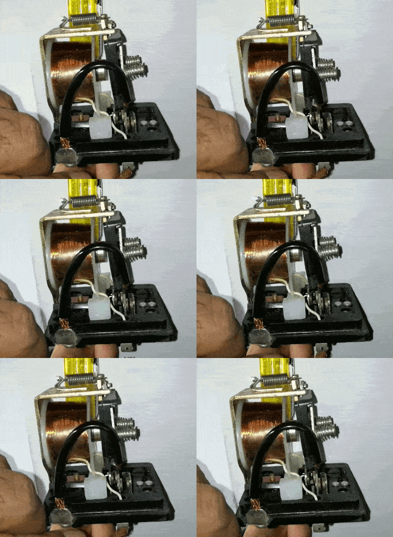
- Relays use the principle of electromagnetism. An electromagnet is activated whenever a slight current is passed through the relay coil. It pulls one switch contact away from another.
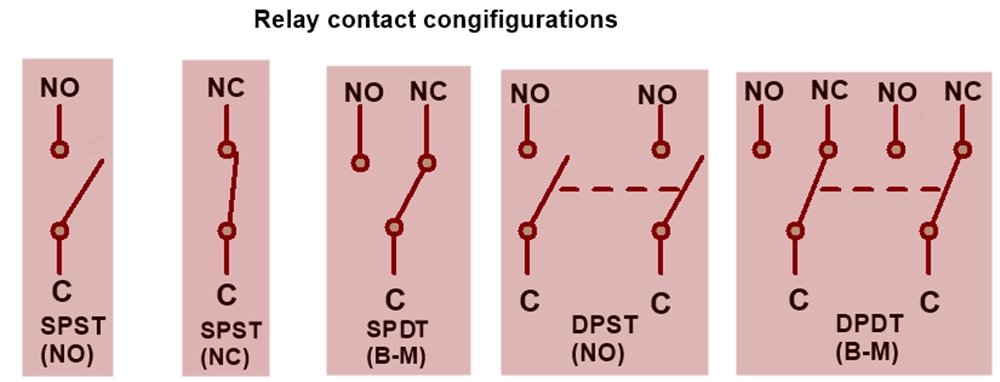
Types of Relay Contacts
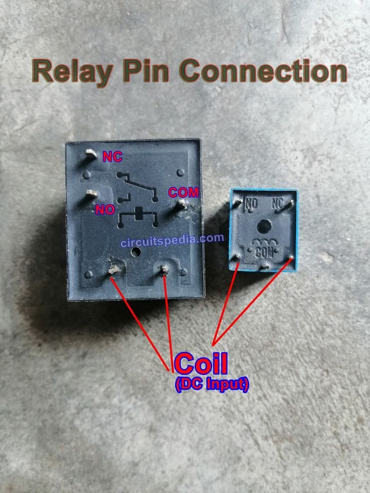
Normally open (NO) and Normally Closed (NC) contacts are two contacts that comprise an ordinary relay. You can switch the common terminal with either NC or NO. Let’s get into more detail about different types of relay contacts.
- NO Terminal: Normally Opened – It refers to the state where the wire linked with this terminal will simply be open and the flow of current will stop when the relay gets inactivated. When the power supply triggers a relay, its internal circuitry gets activated which makes the NO terminal close, and current starts flowing via this terminal. Hence, it is known as normally open as this terminal doesn’t enable the current flow unless triggered by default.
- NC Terminal: Normally connected – It refers to that state where the wire linked with this terminal will simply be closed and current will flow, when the relay gets inactivated. When the power supply triggers a replay, its internal circuitry gets activated which makes the NC terminal open, and current stops flowing via this terminal. Hence, it is known as normally closed as this terminal enables the flow of current unless triggered by default.
- Common or COM Terminal: It refers to the common terminal of the relay. COM terminal is the output of the relay wherein the load circuit is linked at one end. This contact is internally linked with either NO or NC contacts based on the relay’s condition.
Relay Working Principle
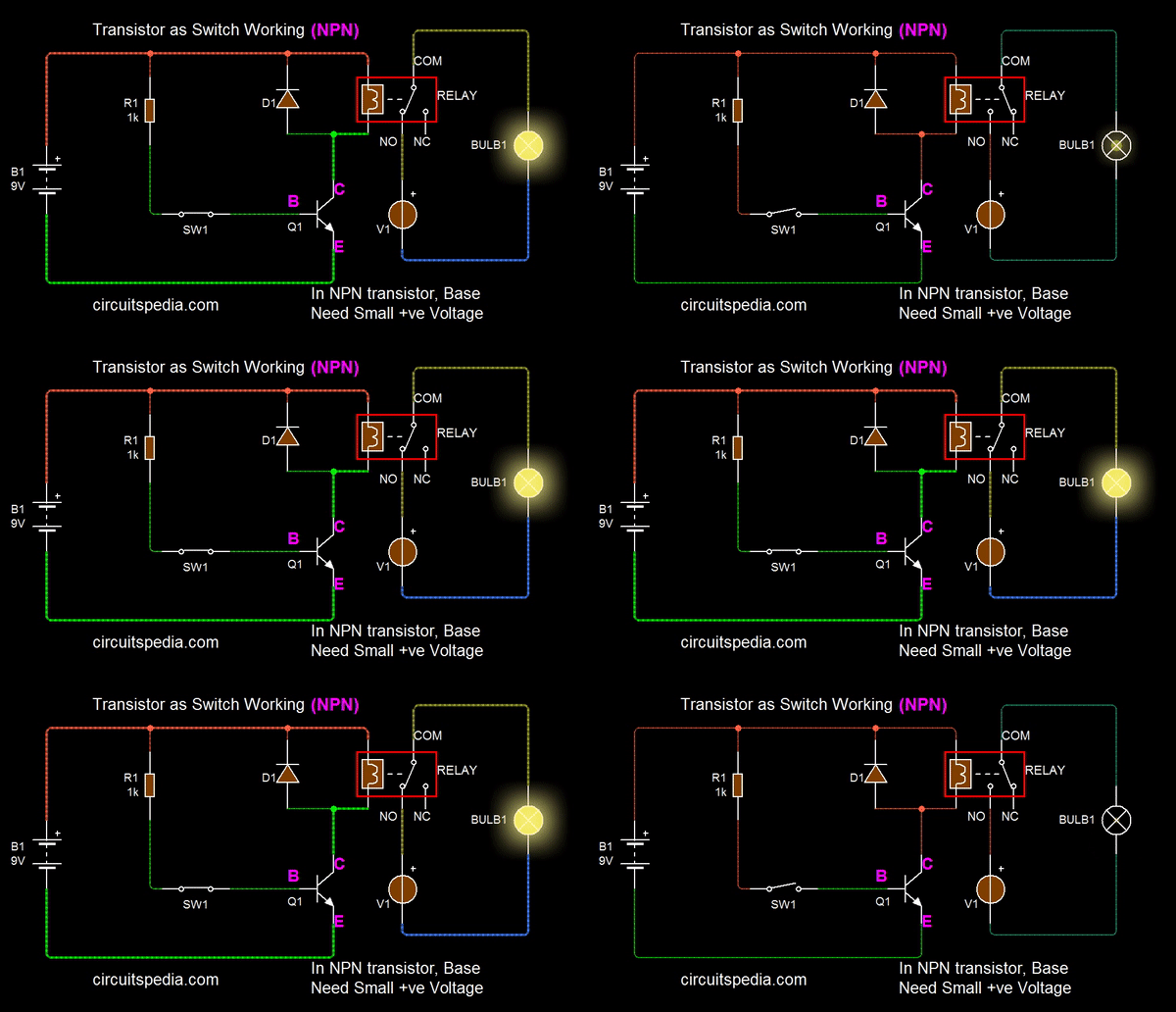
A Relay activates using the magnetic field created by the coil including in the relay module. When voltage is applied to the relay Coil, The coil will create an electromagnetic force, and then by this electromagnetic force the terminals of the relay module will be activated The voltage source can be applied to the coil of the relay using Transistor by the switching mechanism of mostly using NPN transistor. Or in case of AC relay direct voltage to be applied on the coil to activate the relay.
AC Relay Driver Circuit

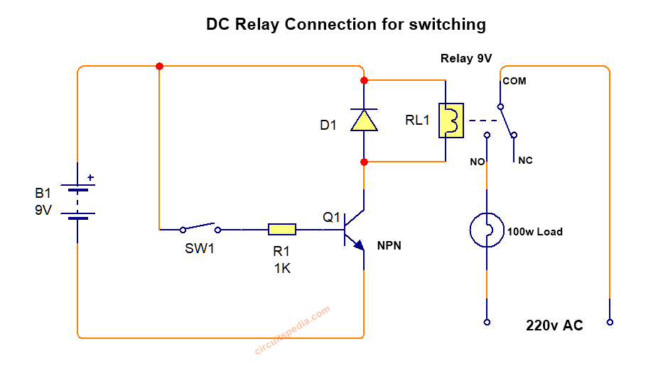
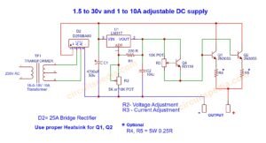
9V DC Relay driver circuit diagram
- A relay driver is a transistor.
- Generally, relays are operated by relay drivers.
- Few sensors help to turn on the transistor.
- When the relay driver gets triggered, it supplies current to an electromagnet. The magnet pulls a metal switch when activated to a proximity location. Hence, it triggers the second high current.
- In the output circuit, a comparatively slight current in the input driver circuit triggers the higher current.
Real-Time Uses of Relays
- Imagine you wish to develop a street light system that operates electronically and switches an electrical bulb ON or OFF concerning the surrounding light intensity.
- Here, an electronic light sensor circuit (LDR) could be used to detect light and dark conditions. However, LDR generates only slight resistance changes as per the light intensity.
- You can link the input circuit of a relay with the LDR circuit through a relay driver.
- When the flow of current from the sensor goes via the circuit, the relay triggers the output circuit enabling a much higher flow of current. Hence, the electrical bulb gets turn ON.
Relay Connection Diagram and Connection Procedure
- Find out the two contacts of the coil. They can be found easily by opening the relay.
- Link Vcc to one contact and fed the other contact to the driver transistor collector.
- Interlink the common contact of the relay with the high current neutral line.
- Then, interlink the NO contact with any of the load contact (Motor, Bulb, and others).
- Interlink the remaining terminal of the load with the phase line directly.
Conclusion:
Countless electrical appliances and electrical sensors made up the electrical engineering industry. Bust as an electronic/electrical enthusiast or electrical engineer, the objectives and setbacks belong to them. Relay helps to fill that gap and understand the core concept of projects. Therefore, detailed knowledge about how to link relay is far more crucial than it looks.



Dear Circuitspedia,
We are pleased to invite your esteemed company to participate in the British Petroleum (BP) Vendor/Contractor Partnership Registration for the 2025/2026 term. This opportunity is open to companies globally, and we are excited about the potential collaborations ahead.
To proceed, kindly express your interest by requesting our Vendor Questionnaire and Expression of Interest (EOI) documents. Your prompt response would be greatly appreciated, as it will help expedite the vendor and contractor selection process.
We look forward to potentially partnering with you and exploring ways to drive mutual growth and success.
James Wilson
Procurement Officer
British Petroleum (BP)
Hi,
I hope this message finds you well.
I’m reaching out because I have a keen interest in contributing a guest post to your website. As a seasoned writer, I specialize in creating content that drives traffic and captivates readers.
I’d be happy to provide a guest post, tailored specifically to your audience’s interests and needs.
If you’re open to this idea, I can share some topic suggestions that I think would resonate well with your readers.
Looking forward to your response.
Best,
Amber
Hi,
I am a senior web developer, highly skilled and with 10+ years of collective web design and development experience, I work in one of the best web development company.
My hourly rate is $8
My expertise includes:
Website design – custom mockups and template designs
Website design and development – theme development, backend customisation
Responsive website – on all screen sizes and devices
Plugins and Extensions Development
Website speed optimisation and SEO on-page optimisation
Website security
Website migration, support and maintenance
If you have a question or requirement to discuss, I would love to help and further discuss it. Please email me at e.solus@gmail.com
Regards,
Sachin
hireadevelopernow@gmail.com
Dear Circuitspedia,
I hope this message finds you well. I am reaching out to inquire about your company’s current capacity availability, as we have an upcoming project slated to commence in the second half of the year. We would appreciate it if you could provide a quotation for your services to help us proceed with planning.
Looking forward to your feedback.
Best regards,
George Silver
Purchasing Manager
Nexans