How to Build a Light Dimming Circuit Using Pushbuttons and MOSFETs
(Fade On Fade OFF circuit)
Introduction
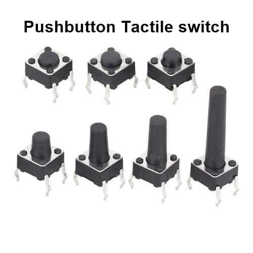
Do you want to build a circuit where a light bulb or LEDs gradually brighten or dim? In other words, a lighting circuit where brightness can be increased or decreased using just one or two push buttons.
When you press the pushbutton, the bulb or LED will gradually increase in brightness, and similarly, by pressing the button again, the brightness will gradually decrease.
This circuit can be used as fancy or decorative lighting. It is quite interesting and requires very few components. Let’s learn how to build this circuit step by step.
Why Build This Circuit?
This project is perfect for beginners and hobbyists who want to learn about electronic components and how they work together. Whether you’re designing mood lighting or just experimenting with circuits, this is a fun and educational build.
In this article, we will learn how to build three different circuits, each with slightly different functionality.
How It Works
The magic behind this circuit lies in the capacitor. When you press the ‘Increase’ button, the capacitor slowly charges, increasing the MOSFET’s gate voltage, which gradually brightens the LED. When you press the ‘Decrease’ button, the capacitor discharges, lowering the gate voltage and dimming the LED smoothly. This creates a soft transition effect rather than an abrupt change in brightness.
Touch Sensitive circuit–
These are Touch-sensitive circuits, By touch You can make a connection between the points that is used by the pushbutton to connect, Use Your figures to touch the point that is connected to a pushbutton
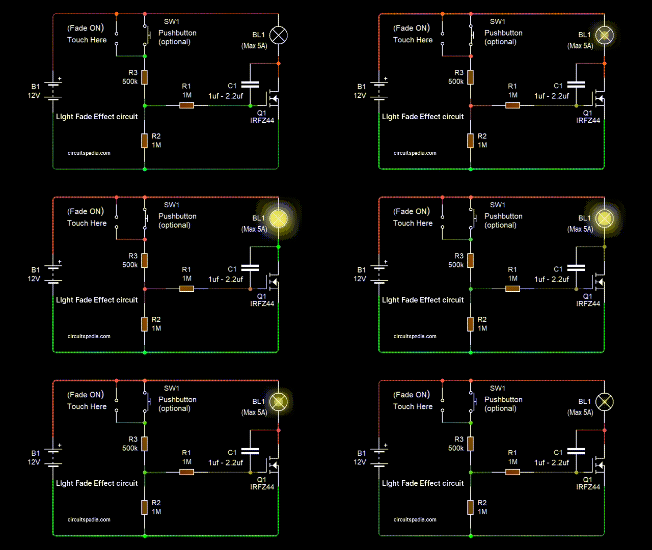
Circuit 1: Auto-Dimming After releasing the button
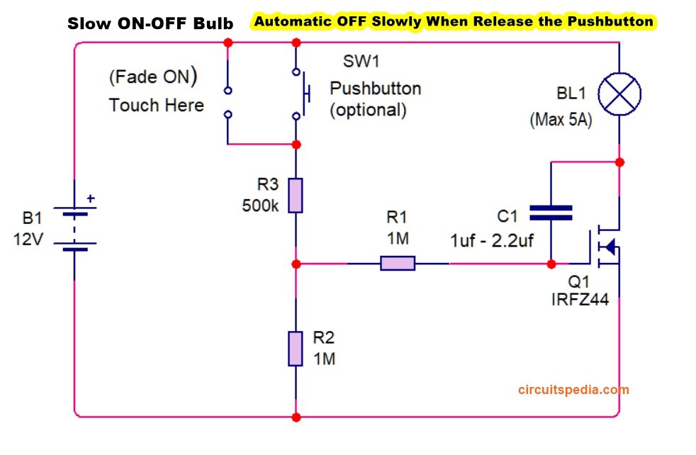
Connections (Refer to the Diagram)
- Connect a 500KΩ and 1MΩ resistor in series between the pushbutton to negative supply (ground).
- Connect one terminal of the pushbutton to the positive supply.
- Connect the MOSFET gate pin between the 500KΩ and 1MΩ resistors.
- Connect a Capacitor between the MOSFET Gate and Drain Pin terminals.
How It Works
- In this circuit, when you press and hold the pushbutton, the LED or light will gradually brighten until it reaches full brightness.
- Once the light is fully bright, it will stay at that level (Until the button is released).
- However, as soon as you release the button, the light will gradually dim and automatically turn off.
- Pressing the button again will gradually increase the brightness again.
Why Does the Light Dim and Turn Off Automatically?
- Two 1MΩ resistors are connected between the MOSFET gate and the negative supply.
- This resistor causes the bulb to gradually dim and turn off automatically when the button is released. This Resistor discharges the connected capacitor slowly.
- If we connect this resistor to the positive supply instead, the circuit will behave oppositely:
- Pressing the button will gradually dim the light.
- Releasing the button will gradually brighten the light to full intensity.
Capacitor Requirement
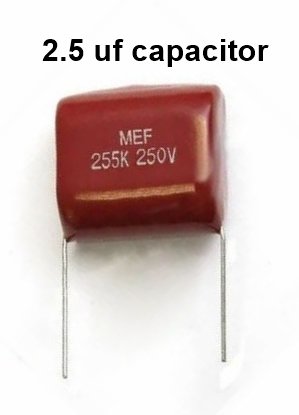
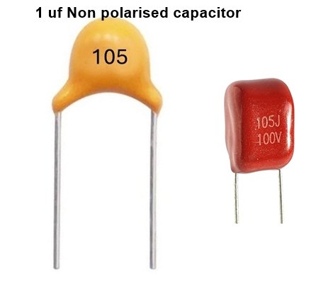
- You can use any ceramic or polyester non-polarized capacitor with a minimum value of 1µF.
Circuit 2: Two-Pushbutton Brightness Control
How It Works
- This circuit uses two pushbuttons:
- One button to increase brightness.
- Another button to decrease brightness.
- The light remains at the last adjusted brightness level when the buttons are released.
Connections
- Connect one pushbutton’s one terminal to positive supply.
- Connect the other pushbutton’s one terminal to negative supply.
- Connect the other terminals of both buttons at a common point.
- Connect a 1MΩ resistor between the MOSFET gate and the common terminal of the pushbuttons.
- Connect the Capacitor between the MOSFET Gate and Drain pins.
Functionality
- When you turn ON the power, the light will be fully bright by default.
- Pressing the first pushbutton will gradually dim the light, and it will turn off completely.
- Pressing the second pushbutton will gradually brighten the light until it reaches full intensity.
- If you hold the first push button, the light will keep dimming.
- If you hold the second push button, the light will keep brightening.
- When you release the button at any dimming level, The dimming status also stays on that level.
Pushbutton Functionality
- The pushbutton connected to the negative supply → DIMS the light. (Fade OFF)
- The pushbutton connected to the positive supply → BRIGHTENS the light. (Fade ON)
Circuit 3: Two-Bulb Alternating Brightness Control
How It Works
- This circuit controls two bulbs, but only one can be fully bright at a time.
- When one bulb increases in brightness, the other bulb automatically dims.
- The two bulbs will alternate in brightness instead of both being fully bright simultaneously.
- Connect one terminal of the pushbutton to the positive supply.
- Connect one terminal of the second pushbutton to the positive supply.
- Connect the other terminal of both pushbuttons.
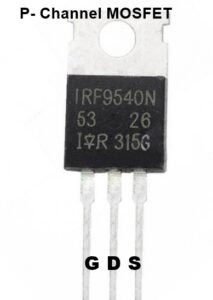
- Use two MOSFETs: One is an N channel (e.g., IRZ44N), and the second is a P-channel MOSFET (e.g., IRF9540). Connect them according to the given diagram.
- Connect one 1M resistor to each MOSFET gate pin.
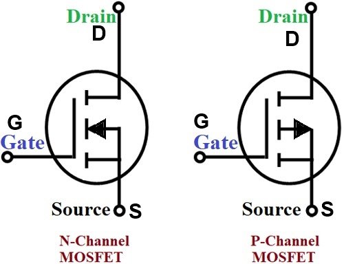
- Keep in mind that The Source in and drain pin connection is reversed as N channel MOSFET (S connected with +ve and drain with -ve across load bulb)
Connections
- Two push buttons are used.
- When one pushbutton is pressed, one bulb gets brighter while the other dims.
- When the other pushbutton is pressed, the effect is reversed.
- This circuit includes an extra P-channel MOSFET.
Why Use a P-Channel MOSFET?
- A P-channel MOSFET conducts when a negative voltage is applied to its gate pin.
- When the push button provides a negative voltage supply to the N-channel MOSFET gate pin, the bulb dims because the N-channel MOSFET does not allow current to flow. At the same time, the P-channel MOSFET receives a negative supply at its gate pin, allowing current to flow through it.
Connection Details
- Connect the positive supply to the P-channel MOSFET source pin.
- Connect the drain pin to one terminal of the load (bulb).
Adjusting Dimming Duration
Dimming Duration Depends on Capacitor Charging/Discharging
The speed of dimming and brightening can be adjusted in two ways:
- Changing the Capacitor Value
- If you want slow dimming, use a higher capacitor value (2µF to 4µF).
- If you want fast dimming, use a lower capacitor value (1µF or less).
- Changing the Resistor Value
- Using a high-value resistor will increase the dimming duration because the capacitor charges/discharges slowly.
- Instead of connecting the pushbutton directly to the power supply, use a 470kΩ or higher resistor in series.
- Both pushbuttons should have a 470kΩ resistor to increase the dimming duration.
Common Issue: Flickering During Dimming
Problem:
- During dimming, a slight flicker or temporary fluctuation in brightness may occur.
- This issue is more common when using a high-value capacitor.
Solution:
- To eliminate this flickering, connect a 0.1µF ceramic or a High-voltage CBB or polyester Film capacitor between the MOSFET gate and source pins.
- This stabilizes the voltage and ensures smooth dimming.
Safety Considerations: Preventing Short Circuits
When using two pushbuttons, pressing both at the same time can short the power supply, causing a circuit failure.
Solution:
- Add a 100kΩ resistor in series with one of the pushbuttons.
- This prevents a direct short circuit and ensures safe operation.
(If you already apply a resistor with a pushbuttons for more delay time of dimming then there is already circuit is protected from this issue.)
Conclusion
These circuits provide a simple and effective way to control light brightness using MOSFETs and pushbuttons. Whether you want automatic dimming with a single button, manual brightness control with two buttons, or alternating brightness between two bulbs, these circuits are easy to build.
By adjusting the capacitor and resistor values, you can modify the dimming speed to suit your needs. Try experimenting with different values and enjoy building your own custom dimming circuit!
You can use Load Upto 5A with MOSFET very easily with a proper heatsink use with this separately. Loads Like High watt LEDs, Normal LEDs, DC bulbs, DC fans. Other DC motors etc. With Motors, You should use a Diode across the Drain pin and +ve supply (Diode In Reverse biased Here).
 Final Thoughts
This simple dimming circuit is a great way to learn about MOSFETs, capacitors, and pushbutton controls. Whether you’re using it for home lighting or as a learning project, it’s an exciting and rewarding experience. Give it a try, tweak the values, and see how you can improve the dimming effect. Happy experimenting!
In the next article, I will discuss How to Replace pushbuttons and make Automatic Dimming On and Dimming OFF Behaviour. Also I try to connect AC Loads (230V bulb) in coming articles.
More from This Site
-
Capacitor code calculator (Code to Value and value to Code)
-
Resistor color code calculator
-
Dark sensor Circuit using LDR and Photodiode

