44 w Stereo Amplifier Circuit for car
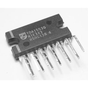
TDA1553 Audio Amplifier IC – Features, Working, and Applications
Introduction
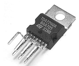
The TDA1553 is a 2 × 22W stereo amplifier IC specifically designed for car audio applications. It is a single-chip solution that requires minimal external components, making it ideal for compact and efficient amplifier circuits. The IC operates in Bridge-Tied Load (BTL) mode, allowing it to drive 4Ω speakers directly without the need for coupling capacitors.
In this blog post, we will explore the circuit connections, working principle, specifications, and applications of the TDA1553 amplifier IC.
TDA1553 is a monolithic ic that is designed for stereo amplifier that can provide at each channel 22 w output power.
Features of TDA1553 IC
- High Output Power: Delivers 2 × 22W output at a 14.4V power supply with 4Ω speakers.
- Bridge-Tied Load (BTL) Configuration: Eliminates the need for output coupling capacitors, improving efficiency.
- Low Distortion & Noise: Produces clear and high-quality audio output.
- Thermal Protection: Includes an automatic thermal shutdown feature to prevent overheating.
- Short Circuit Protection: Prevents damage due to accidental wiring faults.
- Minimal External Components: Requires only a few resistors and capacitors, making it easy to design compact circuits.
- Wide Operating Voltage: Works efficiently within 12V–18V, making it suitable for car and home audio systems.
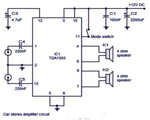
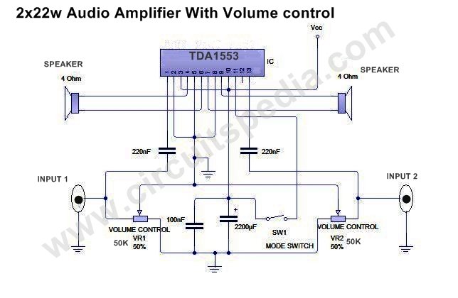
TDA1553 Circuit Diagram & Connections
A basic stereo amplifier circuit using the TDA1553 IC consists of:
- Power Supply: A 12V–18V DC supply to power the IC.
- Audio Input: The left and right channel audio inputs are fed to the IC via capacitors to block DC components.
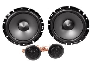
- Speaker Output: Two 4Ω or 8Ω speakers are connected to the output pins of the IC.
- Decoupling Capacitors: A 100µF capacitor is used to stabilize the power supply and filter out noise.
Pin Configuration:
| Pin No. | Function |
|---|---|
| 1 & 8 | Audio Inputs (Left & Right) |
| 3 & 6 | Output to Speakers |
| 4 | Ground |
| 5 | Mute/Standby Control |
| 9 | Power Supply (Vcc) |
Working Principle of TDA1553
-
Audio Signal Processing:
- The left and right audio input signals are fed to the amplifier through capacitors that remove any DC offset.
- The IC amplifies the audio signals based on its internal gain settings.
-
BTL Amplification:
- The TDA1553 operates in BTL mode, meaning each speaker is connected between two active output terminals rather than ground.
- This doubles the voltage swing across the speaker, increasing output power and efficiency.
-
Output Stage & Speaker Drive:
- The amplified signals are delivered to the left and right speakers, providing powerful stereo sound.
- The IC can directly drive 4Ω speakers without additional components.
-
Protection Features:
- If the IC overheats, it automatically shuts down to prevent damage.
- In case of short circuits, the IC enters protection mode to avoid burnout.
Applications of TDA1553
- Car Stereo Systems: Used in automobile sound systems for high-quality audio.
- Portable Audio Systems: Ideal for battery-operated and compact music players.
- Home Theater Systems: Can be used for stereo speaker setups.
- TV & Multimedia Speakers: Suitable for TV sound amplification.
- DIY Audio Projects: Popular among electronics hobbyists for building simple and powerful amplifie
components-
capacitor–
220nf (224)-2
4.7uf, 50v- 1
2200uf, 50v-1
100nf (104) -1
switch-1
IC– TDA1553 – 1
Speaker-2
- Must Read Tone (Bass-Trebble) Controller Circuit
- Dark sensor circuit

