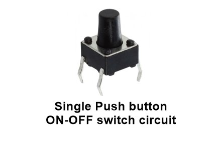
single push button on/off circuit
one push button start-stop relay circuit
Press the switch- ON
Again, press the switch- OFF
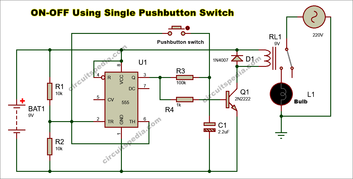
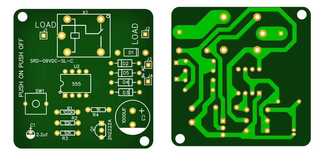
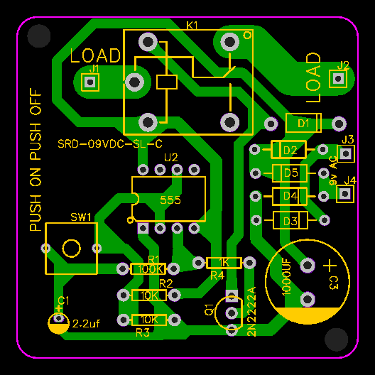
There are the following two circuit diagrams of ON-OFF using a single pushbutton switch. Only one Pushbutton switch is used for both ON and OFF. Once the Load is ON, then remains in this position unless and until pressing again the push button. This type of switch is also called a Latch switch or we can say Toggle switch. First, start the input Power supply to the circuit. Then, the output pin 3 of the IC 555 timer is in LOW means there is no Output. and this condition, the Relay connected to this Circuit is also deactivated, and the load is not turned ON.
The first time, Press the Pushbutton for a moment, then the Output Pin 3 of 555 ic is HIGH, and the Transistor connected with this pin is O.N. Then the Relay will also be Active, and the connected Load will switch ON. And Output will not return to the OFF state unless and until again press the button switch.
Again, the second Time, press the Push button for a moment ( about half to 1 second) then the output will again be in LOW and the relay will be deactivated, and the connected load through the relay will be switched OFF. The output will not go to turn ON unless and until the pushbutton switch is pressed again. So these are simple, Interesting, and very Effective and Useful circuits.
You can use these circuits as a single-phase motor starter (Tullu Pump). If you start the motor and the Electricity cut during this period and you forget to switch it off, then there is a need to restart it again after the power comes.
Push-ON
Push-OFF
Components and parts
IC 555 -1
Resistors (1/4w)
10KΩ- 2
1KΩ-1
100KΩ-1
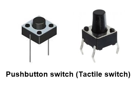
Pushbutton Switch (Tactile switch) -1
Capacitor 2.2uf 25v- 1
Diode 1N4007 -1
Relay 9v 30A- 1
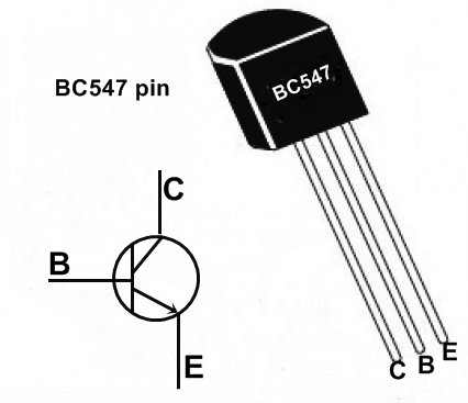
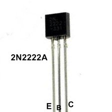
Transistor- BC547 or 2N2222A- 1
Push ON Push OFF using a single Pushbutton switch
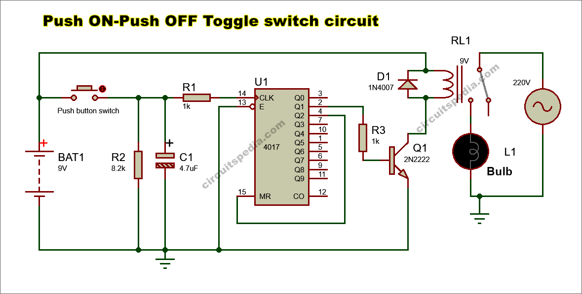
This circuit is built using the Decade counter IC 4017. Pin 14 is the clock input pin of this IC, and this is connected to the switch through a 1k resistor. IC 4017 has 10 outputs, but in this connection, only 2 outputs are used, and the output is connected only with one pin.
At first, the circuit is ON by connecting the input power supply. The output at pin 3 will be HIGH; because no connection on that pin, our Load will remain in OFF.
When the button is pressed, the Clock signal (LOW to HIGH) is applied at pin 14, and the output is shifted from (Q0 to Q1) pin 3 to pin 2. The transistor will turn on and the Relay is activated, and the Load will be ON.
Again pressing the button switch again a clock signal goes at pin 14 of IC4017 and now Output shifted again (Q1 to Q0) From pin 2 to pin 3 and Pin has No output and our load will turn OFF.
For applying the clock signal on pin 14, a resistor of 8.2k is connected in parallel with an electrolyte capacitor of 4.7uf. Use a battery or AC adaptor for an input power supply of 6v to 12v and use transistor BC547 for a small size relay If you have a Big size Relay, then you should use a 2N2222A. This is also a very simple, interesting, and useful circuit. This circuit also can be used as a starter for a one-phase Tullu Motor Pump.
Parts and components
IC4017-1
Resistors – 8.2kΩ-1, 1kΩ-2
Capacitor- 4.7uf 25v -1
Transistor – 2N2222A -1
Relay 9v – 1
Diode 1N4007- 1
Pushbutton Tactile switch – 1
Simulation Video
TESTING VIDEO
One pushbutton on off relay switch circuit. | ON-OFF using single push button switch simulation
Also read
- Bird sound generator circuit using Arduino
- Dark sensor circuit for Auto ON-OFF Light
- How does a capacitor block DC and Pass AC
- Logic gate circuit (AND, OR, NOT, EXOR, EXNOR etc)

